Pump transmission with PTO gear and independently clutched impeller

a technology of pump transmission and clutch, applied in the direction of belt/chain/gearing, mechanical equipment, belt/chain/gearing, etc., to achieve the effect of prolonging the life of the pump

Active Publication Date: 2015-03-24
W S DARLEY & CO
View PDF23 Cites 17 Cited by
  • Summary
  • Abstract
  • Description
  • Claims
  • Application Information

AI Technical Summary

Benefits of technology

[0008]While the prior pump transmissions power a primary device and also allow for the powering of an auxiliary device or devices, they are limited such that in order to power a PTO gear within the casing of the transmission, the pump or impeller shaft must be powered. This has not been viewed as a problem but, rather, a fact of life or a necessary aspect of such devices. Heretofore there was little or no purpose in decoupling the pump from the PTO device since auxiliary devices used in conjunction with the pump or pump transmission require the pump. Indeed, auxiliary devices such as compressors or boosters require the pump and its water in order to operate. The present inventors have recognized, however, that running the PTO gear without running the impeller shaft would provide numerous benefits, such as prolonging pump life, allowing for running of an auxiliary device in situations where pump water is scarce or lacking, providing versatility options for a pump transmission to power a variety of devices that otherwise would not be justified running due to excessive pump wear, among many other benefits. The present inventors have also recognized that since the PTO gear may be driven independently from the pump, the particular features of the PTO gear can also be independent of the pump. For instance, the type and size of the PTO gear does not have to be influenced by the speed requirements or other particulars of the pump. A spur gear, instead of a helical gear may be used for the PTO gear. Different gear spacing and helix angles, the number of gear teeth, and other aspects of the gearing can be modified or used to accommodate compatibility with a variety of auxiliary and PTO devices. Advantageously, the PTO gear may be configured to engage with a Commercially Available (instead of a specially designed) PTO device. Thus, running the PTO gear without running the impeller shaft provides even further benefits.
[0009]Affixing a PTO device 50 (such as a Commercially Available PTO device) to the pump transmission 20 for powering an auxiliary device which is not useful or not critical to the operation of the pump would not make sense, for in order to run the auxiliary device would necessarily require driving the impeller shaft 40. Preferably the impeller shaft is run only when required in order to preserve the useful life of the pump. Typically, the pump impeller is driven only a small percentage of the time an emergency vehicle is called to action in the field. As such, configuring the PTO device to operate independently of the impeller shaft provides further benefits.
[0010]In accordance with the invention, then, the versatility of a firefighting pump transmission is enhanced by independently powering, from a common drive shaft, a PTO gear and an impeller shaft. Such arrangement allows for independent use of an auxiliary device without having to run the pump, and among other benefits, also accommodates use of a variety of auxiliary devices heretofore otherwise being impractical for use with a pump transmission.

Problems solved by technology

While the prior pump transmissions power a primary device and also allow for the powering of an auxiliary device or devices, they are limited such that in order to power a PTO gear within the casing of the transmission, the pump or impeller shaft must be powered.

Method used


Image

  • Pump transmission with PTO gear and independently clutched impeller
  • Pump transmission with PTO gear and independently clutched impeller
  • Pump transmission with PTO gear and independently clutched impeller

Examples


Embodiment Construction

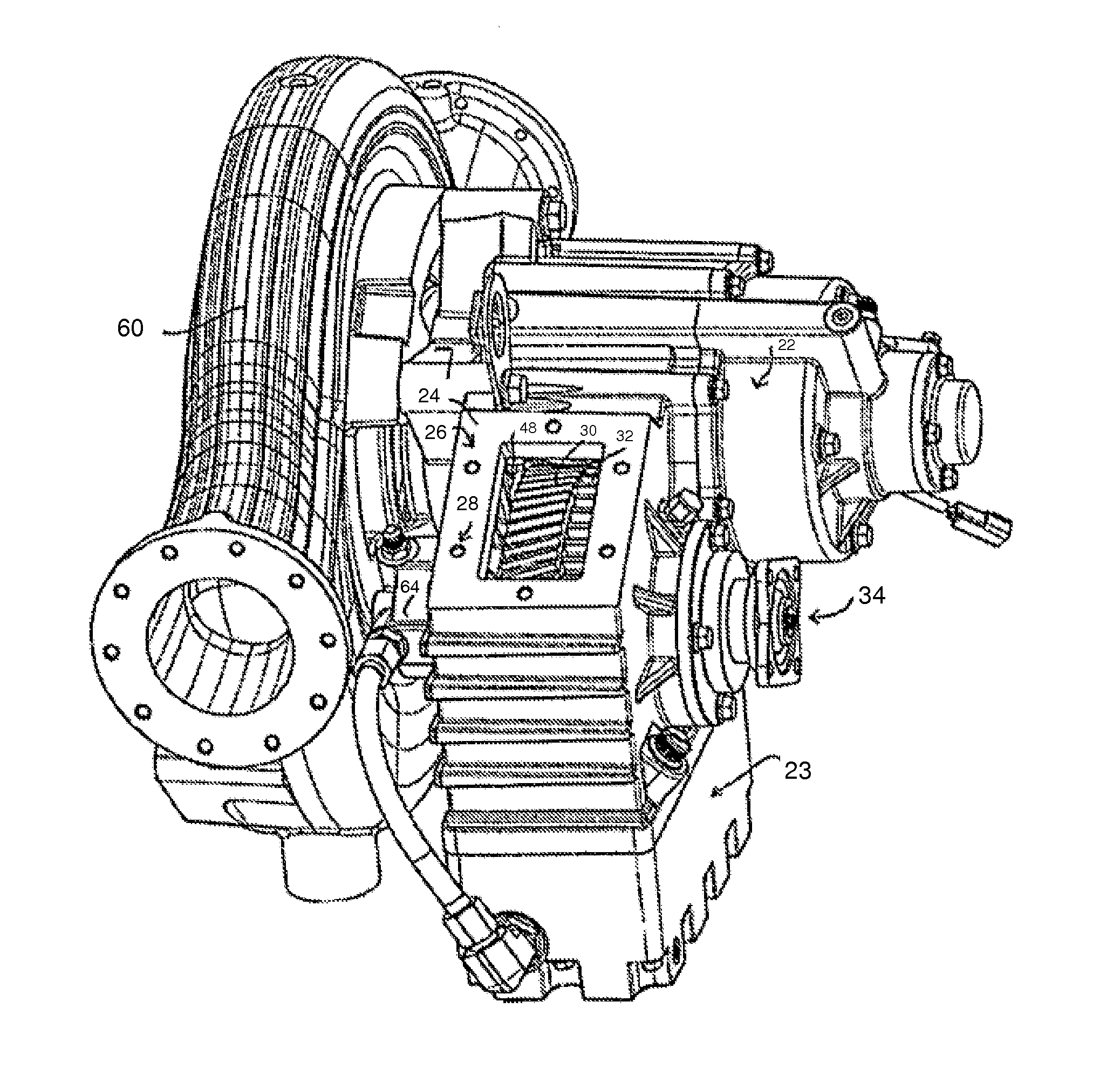
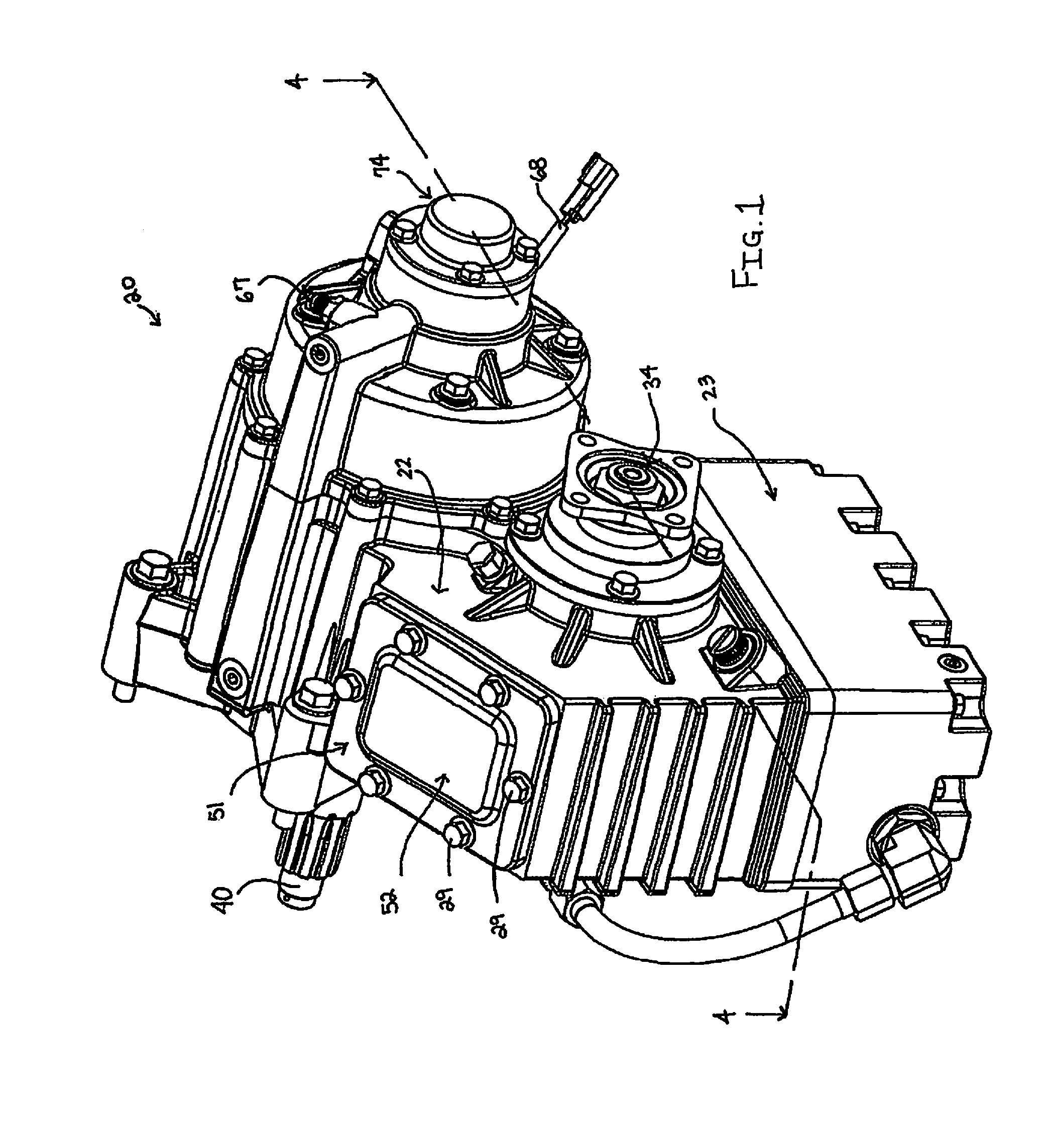
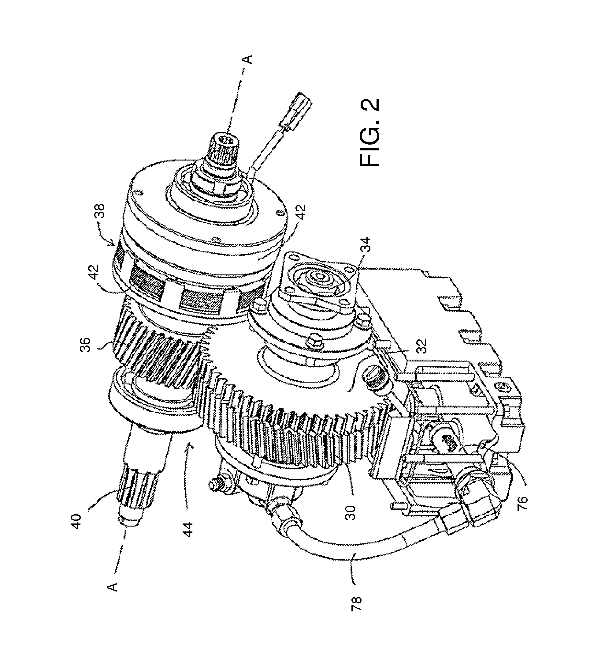
[0035]Among the pumps and pump transmissions known in the prior art are those referenced above in the background section and the device shown in FIG. 14. The FIG. 14 device shows a pump / pump transmission 200. An input shaft (which is a shaft positioned opposite output shaft 210) enters the housing of the transmission 220 at a front portion of the transmission 220. An auxiliary transmission 230 is mounted to the side of the transmission 220. The auxiliary transmission 230 powers a smaller pump 240 which is fed by a hose 250. In this prior system, pump 240 operates as a booster for the pump / pump transmission 200, achieving higher pressures than the pump 200 would otherwise achieve.

[0036]The auxiliary transmission 230 is equipped with a sliding clutch gear (not shown) to engage or disengage the PTO driven device 240. In the illustrated case, the driven device (auxiliary) is the smaller pump 240. The PTO driven device 240 might alternatively be a compressor. The transmission 230 is a tw...


PUM


Abstract

A firefighting pump transmission for use with an emergency vehicle pump comprising a housing receiving a drive shaft, the drive shaft having a PTO gear affixed thereto within the housing, an impeller shaft for turning an impeller of a pump, and means for selectively powering the impeller shaft from the drive shaft, the means for powering may include a multi-disk clutch. The transmission allows for powering the PTO gear while the impeller shaft is idle. A Commercially Available PTO device may be mounted to the housing to power a variety of devices.

Description

CROSS-REFERENCE TO RELATED APPLICATIONS[0001]Applicant claims priority based on Provisional Patent Application No. 60 / 870,086, filed Dec. 14, 2006, the entirety of which is incorporated herein by reference.BACKGROUND OF THE INVENTION[0002]1. Field of the Invention[0003]The present invention relates generally to transmissions capable of powering multiple devices from a single drive shaft, and more specifically to pumps and pump transmissions capable of powering an impeller shaft of a fluid pump and at least another device, and particularly to emergency vehicle pumps and transmissions of such variety.[0004]2. Background Information[0005]Transmissions capable of powering a primary device and at least another device are not new. Some transmissions, especially in the automotive or truck areas, include a drive for powering a primary device, such as an axle of the vehicle, and may also include a power take-off, commonly known as a PTO. A PTO device is designed to power an auxiliary device,...

Claims


Application Information

Patent Timeline
Patent Type & Authority Patents(United States)
IPC IPC(8): F16H37/00A62C25/00
CPCA62C25/005
Inventor SEITZ, DOUGLAS W.RUTHY, MICHAEL C.
Owner W S DARLEY & CO
Why Eureka
Try Eureka