Sheet manufacturing apparatus

a technology of sheet metal and manufacturing apparatus, which is applied in the direction of chemistry apparatus and processes, instruments, papermaking, etc., can solve the problems of not being determined and users cannot recognize the generation of clogging

Active Publication Date: 2015-03-24
SEIKO EPSON CORP
View PDF3 Cites 18 Cited by
  • Summary
  • Abstract
  • Description
  • Claims
  • Application Information

AI Technical Summary

Benefits of technology

[0009]When the clogging was generated in the screen portion, it becomes a resistance for the material that flows into the screen portion or flows out from the screen portion. Therefore, the flow rate of the material is reduced. With this structure, by obtaining the information of flow rate for the inflow to the screen portion or the information of the flow rate for the outflow from the screen portion, the clogging of the screen portion can be determined.
[0024]In the sheet manufacturing apparatus according to the aforementioned example, when the determination that the clogging is generated in the screen portion is made, the flow rate of the material that flows into the screen portion is increased.
[0025]With this structure, the lowering of the flow rate of the material, which flows into the screen portion, caused by the generation of clogging can be suppressed.

Problems solved by technology

However, there was a problem that even when the clogging was generated, it could not be determined.
Further, there was a problem that the user cannot recognize the generation of clogging.

Method used


Image

  • Sheet manufacturing apparatus
  • Sheet manufacturing apparatus
  • Sheet manufacturing apparatus

Examples


first embodiment

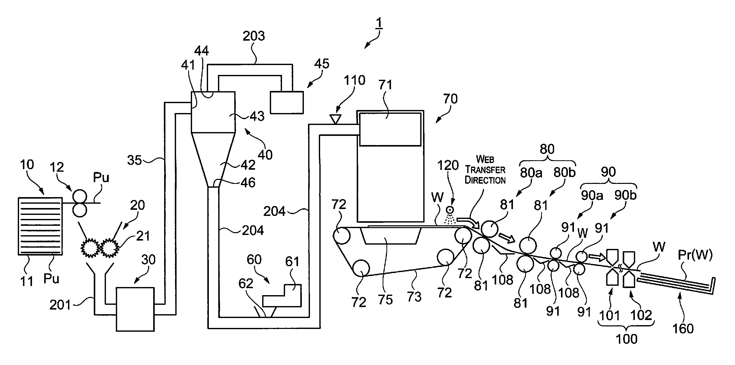
[0042]Initially, a structure of a sheet manufacturing apparatus according to this embodiment will be explained. The sheet manufacturing apparatus is provided based on the technology that recycles a stock material (defibration object) such as, e.g., a used paper, a pulp sheet, etc. to a new sheet. A plurality of openings is provided, and a screen portion in which an introduced material passes through the openings is provided. When a flow rate was reduced, there is a function that a clogging of the screen portion is detected based on at least one of inflow information related to a flow rate of material that flows into the screen portion and outflow information related to a flow rate of material that passes through the screen portion. A stock material as a defibration object supplied to the sheet manufacturing apparatus according to the present embodiment is, for example, used paper (stock material PU) of A4 size, etc., which is a mainstream size in offices. Hereinafter, concrete expla...

second embodiment

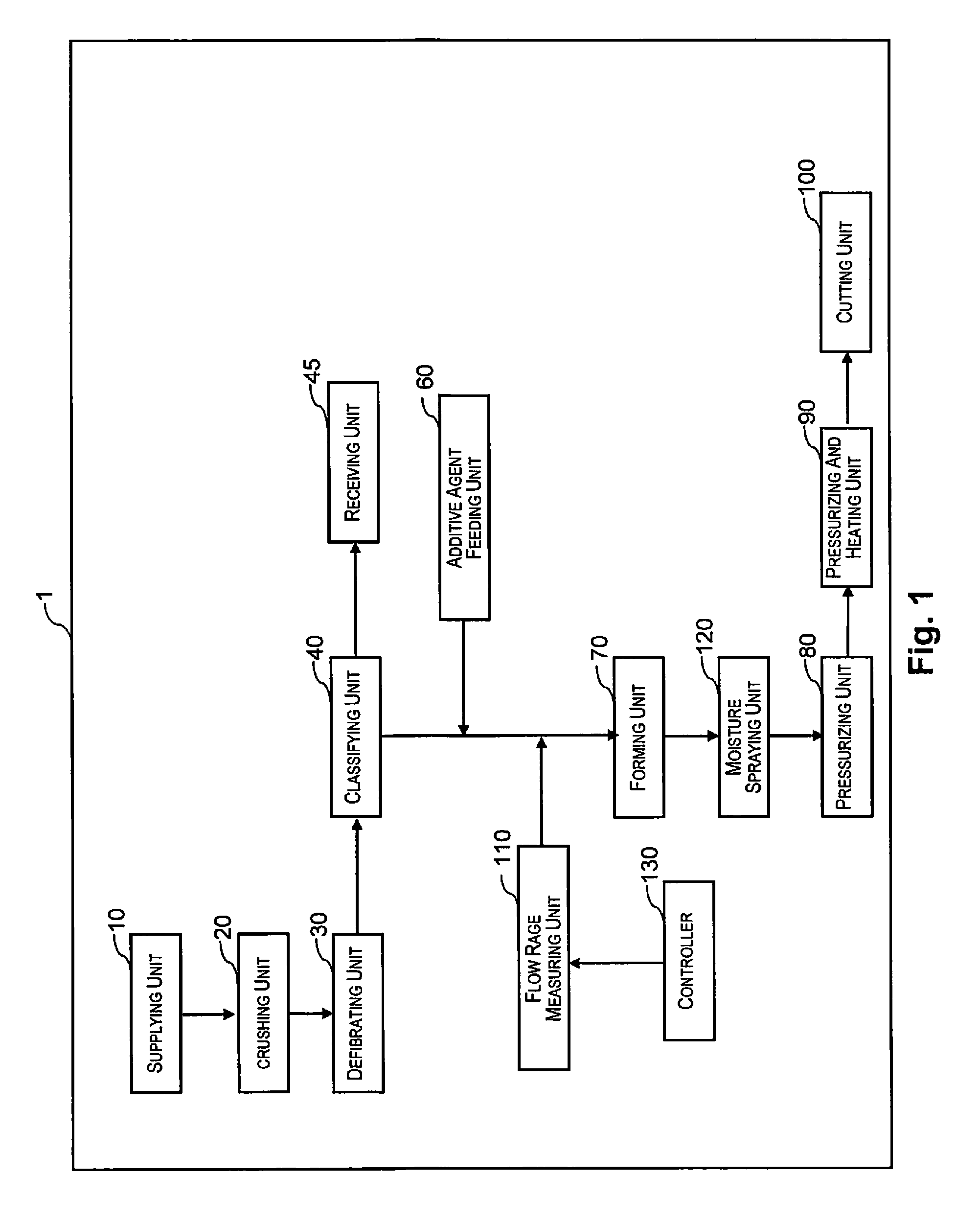
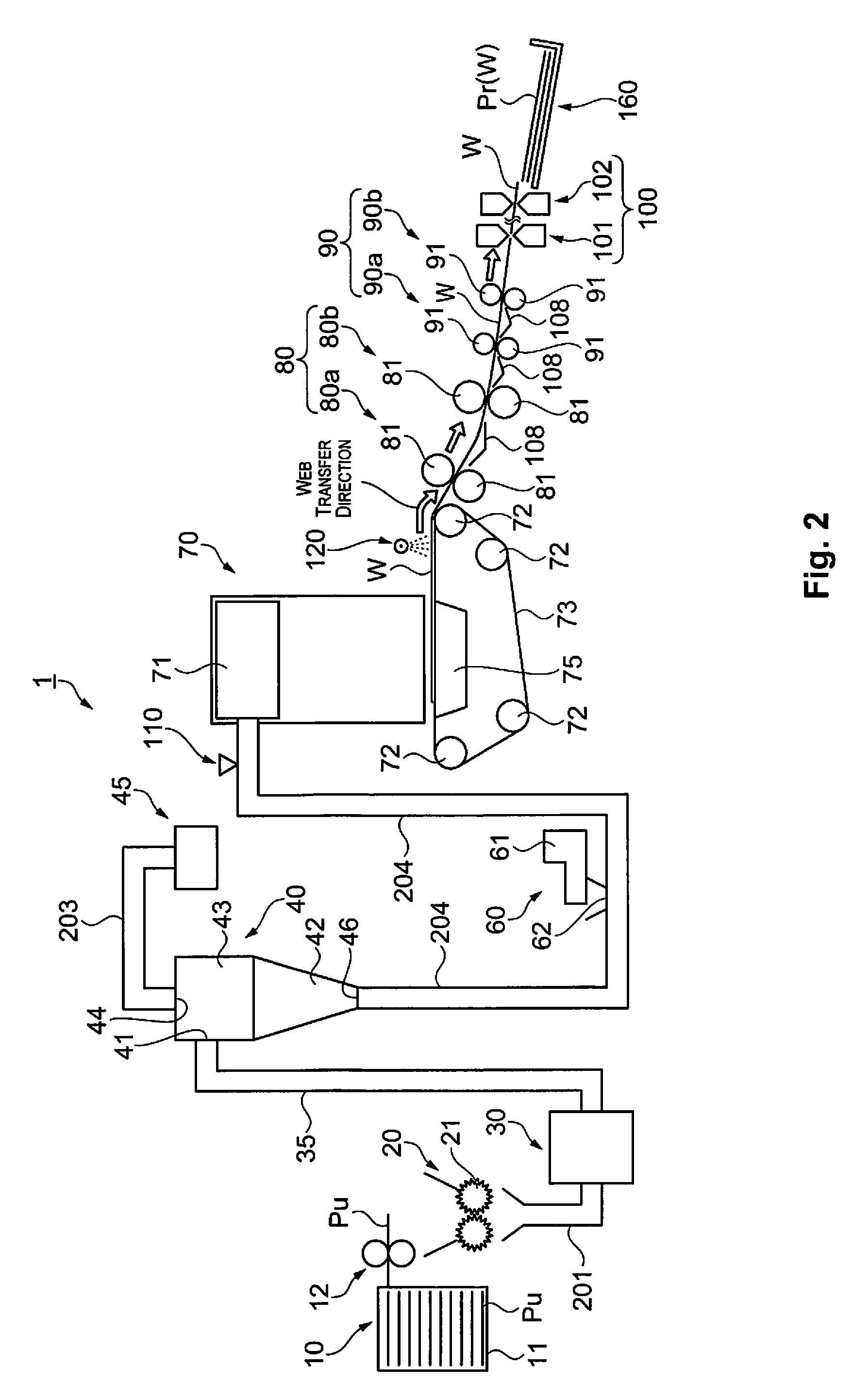
[0073]Next, the second embodiment will be explained. FIGS. 4 and 5 are a schematic view showing a structure of the sheet manufacturing apparatus according to the present embodiment. According to FIGS. 4 and 5, the sheet manufacturing apparatus 1a is provided with a supplying unit 10, a crushing unit 20, a defibrating unit 30, a classifying unit 40, a receiving unit 45, an additive agent feeding unit 60, a forming unit 70, a moisture spraying unit 120, a pressurizing unit 80, a pressurizing and heating unit 90, and a cutting unit 100. Further, a flow rate measuring unit 110 as an information acquiring unit that acquires the outflow information is provided. And, in the sheet manufacturing apparatus 1a, a controller 130 that controls these units is provided.

[0074]The flow rate measuring unit 110 of the present embodiment is provided inside of the air release pipe 76 that releases air, which was suctioned by the suction apparatus 75 of the forming unit 70, to outside of the sheet manufa...

third embodiment

[0083]Next, the third embodiment will be explained. FIGS. 7 and 8 are a schematic view showing a structure of the sheet manufacturing apparatus according to the present embodiment. According to FIGS. 7 and 8, the sheet manufacturing apparatus 1b is provided with a supplying unit 10, a crushing unit 20, a defibrating unit 30, a classifying unit 40, a receiving unit 45, an additive agent feeding unit 60, a forming unit 70, a moisture spraying unit 120, a pressurizing unit 80, a pressurizing and heating unit 90, and a cutting unit 100. Further, a torque amount measuring unit 111 as an information acquiring unit that acquires the outflow information is provided. And, in the sheet manufacturing apparatus 1b, a controller 130 that controls these units is provided.

[0084]The torque amount measuring unit 111 of the present embodiment measures current value, which drives the suction apparatus 75 of the forming unit 70, or torque value applied to the suction apparatus 75 as outflow information...


PUM

PropertyMeasurementUnit
flow rateaaaaaaaaaa
thicknessaaaaaaaaaa
weightaaaaaaaaaa

Abstract

A sheet manufacturing apparatus is provided with a screen portion in which introduced material is passed through a plurality of openings; an information acquiring unit configured to acquire at least one of inflow information related to a flow rate of the material that flows into the screen portion and outflow information related to a flow rate of the material that passes through the screen portion; and a controller configured to make a determination that a clogging of the screen portion is generated when the flow rate is reduced based on at least one of the inflow information and the outflow information.

Description

CROSS-REFERENCE TO RELATED APPLICATIONS[0001]This application claims priority to Japanese Patent Application No. 2013-065810 filed on Mar. 27, 2013 and Japanese Patent Application No. 2014-025125 filed on Feb. 13, 2014. The entire disclosure of Japanese Patent Application Nos. 2013-065810 and 2014-025125 is hereby incorporated herein by reference.BACKGROUND[0002]1. Technical Field[0003]The present invention related to a sheet manufacturing apparatus.[0004]2. Related Art[0005]In used paper discharged from offices, used paper describing confidential matters is included. Therefore, from the viewpoint of security protection, it is also desired that such used paper can be processed in their offices. In small offices, a wet-type sheet manufacturing apparatus, which uses a large amount of water, cannot be suitably used, and therefore a dry-type sheet manufacturing apparatus simplified in structure has been proposed (see, for example, Japanese Unexamined Laid-open Patent Application No. 201...

Claims


Application Information

Patent Timeline
Patent Type & Authority Patents(United States)
IPC IPC(8): D21F1/06B07B1/00
CPCB07B1/00B07B1/42D21B1/08D21F9/00Y02W30/64
Inventor OGUCHI, YUKISEKI, SHUNICHI
Owner SEIKO EPSON CORP
Why Eureka
Try Eureka