Low pressure drop thermal by-pass valve

a technology of thermal bypass valve and low pressure drop, which is applied in the direction of lighting and heating apparatus, process and machine control, instruments, etc., can solve the problems of cumulative damage to the transmission system, high cost, and high cost of the system, so as to achieve the effect of reducing the cost of the system

Inactive Publication Date: 2015-03-31
DANA CANADA CORP
View PDF27 Cites 19 Cited by
  • Summary
  • Abstract
  • Description
  • Claims
  • Application Information

AI Technical Summary

Benefits of technology

[0005]Although these known thermal by-pass valves have worked reasonably well for their intended purpose, improvements to the operating efficiencies of such valves are desirable. One such improvement is to reduce the amount of pressure drop in the circuit during operation of the valve, thereby improving the flow of oil through the circuit and through the valve. It is also desirable to reduce the amount of leakage in the by-pass valve while it is operating in cooler mode, that is with oil flowing through the heat exchanger to which the valve is attached.SUMMARY OF THE INVENTION

Problems solved by technology

However, when the transmission is cold, such as at start-up conditions, the transmission oil is very viscous and does not flow easily through the heat exchanger, if at all.
In such cases, the transmission can be starved of oil and this may cause damage or at least erratic performance.
Cumulative damage to the transmission can also occur if the quality of oil returned is adequate but is overcooled due to low ambient temperatures.
In this case, for instance, moisture condensation in the oil (that would otherwise be vaporized at higher temperatures) may accumulate and cause corrosion or oil degradation.

Method used


Image

  • Low pressure drop thermal by-pass valve
  • Low pressure drop thermal by-pass valve
  • Low pressure drop thermal by-pass valve

Examples


Embodiment Construction

[0027]In the detailed description which follows, exemplary embodiments are described, particularly with reference to the figures appended hereto. However, the particularly disclosed embodiments are merely illustrative thermal by-pass valves for a heat exchange circuit according to the present disclosure.

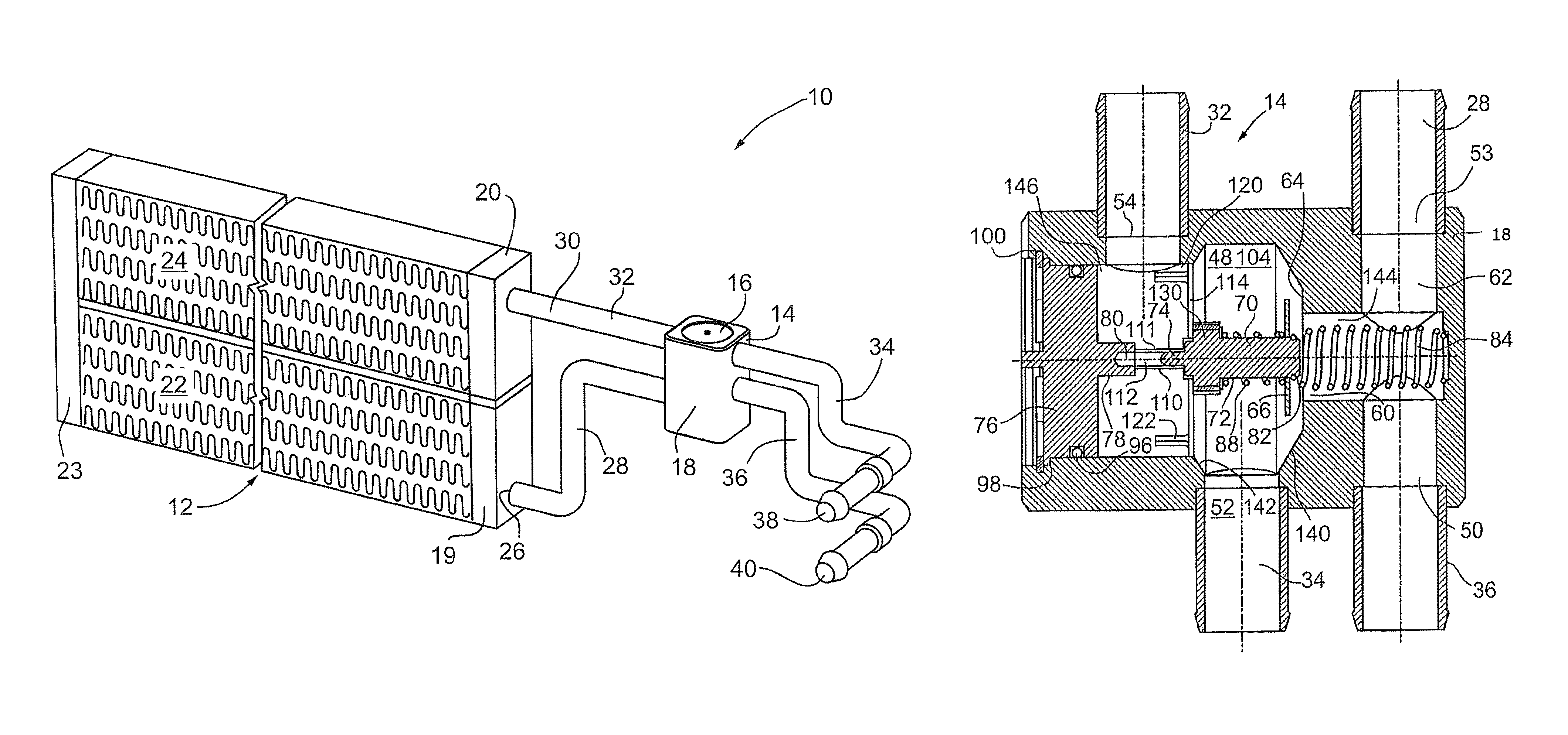
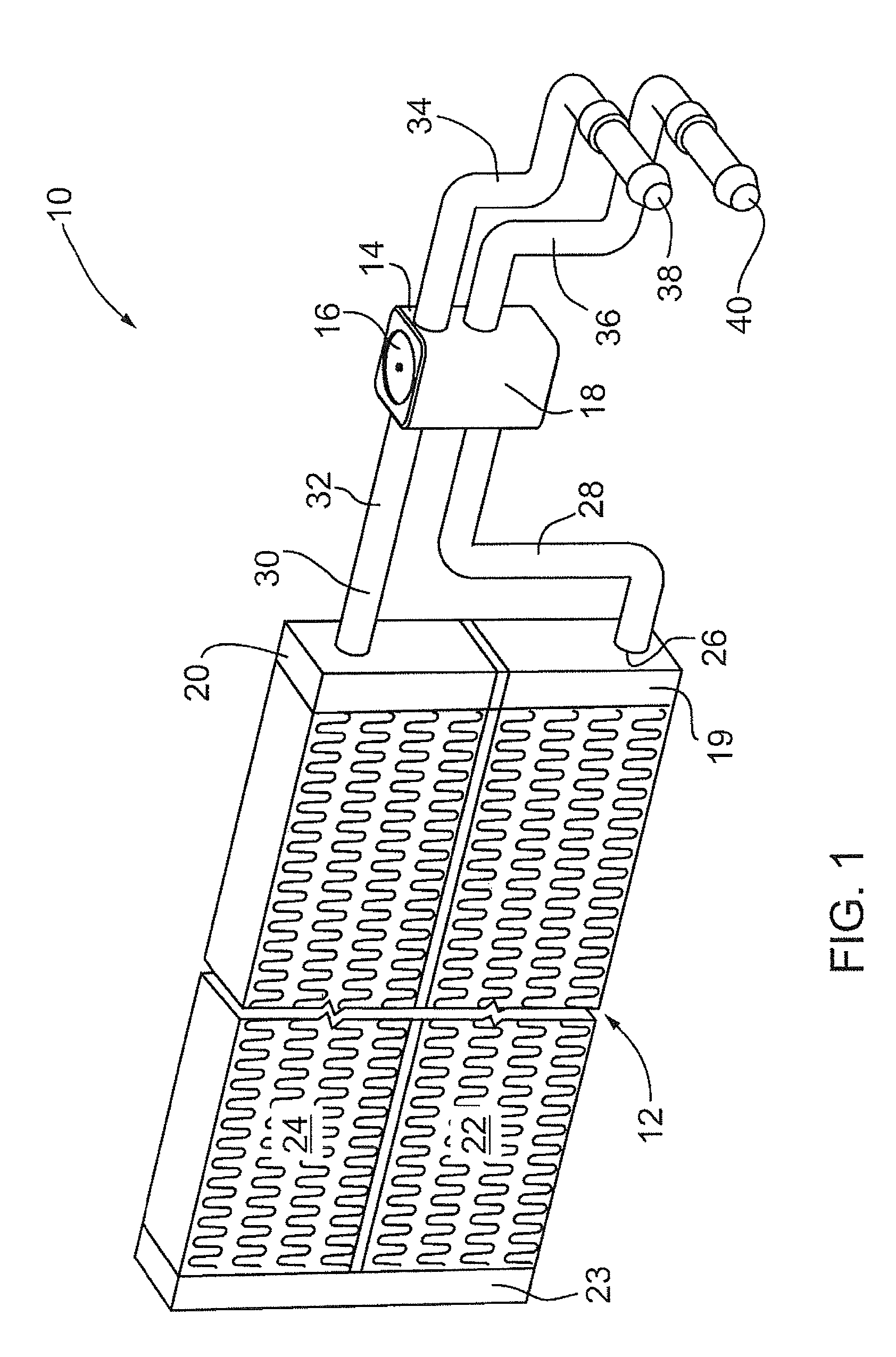
[0028]Referring now to the figures, wherein like reference numerals identify similar structural elements of the apparatus and valve, FIG. 1 illustrates a heat exchange circuit 10, which includes a heat exchanger 12 and one embodiment of a thermal by-pass valve 14 shown with its housing cap 16 at the top of valve housing 18. Any type of heat exchanger can be used with the present invention. A typical two pass heat exchanger is shown in both of FIGS. 1 and 2 and has a first manifold 19 which is an inlet manifold and a second manifold 20 which is an outlet manifold. A plurality of spaced-apart heat exchange conduits 22, 24 are connected between the manifolds, so, for example, the heat e...


PUM


Abstract

A thermal by-pass valve for a heat exchange circuit includes a housing forming a chamber and a by-pass valve port surrounded by a valve seat. The valve port is located between first and second sections of the chamber. First and second oil ports open into the first section. At least a third port opens into the second section. A thermally sensitive actuator is mounted in the first section and has a body and a piston located at one end. The body is movable in the chamber in response to extension of the piston. A valve member is operably mounted on the body and is movable by extension of the piston. A spacer projects from and is connected to the body and forms a passage through which the piston extends. The spacer acts to maintain the adjacent end of the actuator body at least the length of the passage away from an end of the chamber. The spacer can have a valve portion to close a further valve port.

Description

[0001]This invention relates to valves for by-passing a heat exchanger in a heat exchange circuit under conditions where the heat transfer function of the heat exchanger is not required or is only intermittently required.[0002]In certain applications, such as in the automotive industry, heat exchangers are used to cool or heat certain fluids, such as engine oil or transmission fluid or oil. In the case of transmission fluid, for instance, a heat exchanger is used to cool the transmission fluid. The heat exchanger is usually located remote from the transmission and receives hot transmission oil from the transmission through supply tubing, cools it, and delivers it back to the transmission again through return tubing. However, when the transmission is cold, such as at start-up conditions, the transmission oil is very viscous and does not flow easily through the heat exchanger, if at all. In such cases, the transmission can be starved of oil and this may cause damage or at least errati...

Claims


Application Information

Patent Timeline
Patent Type & Authority Patents(United States)
IPC IPC(8): F01P7/14F01P7/16F01M5/00F16H57/04G05D23/02
CPCF01M5/007F16H57/0413G05D23/022G05D23/1333F25B41/20
Inventor SHEPPARD, JEFFREY OWEN
Owner DANA CANADA CORP
Why Eureka
Try Eureka