
Evaluation of etching conditions for pattern-forming film

a pattern-forming film and etching condition technology, applied in the direction of semiconductor/solid-state device testing/measurement, instruments, photomechanical equipment, etc., can solve the problems of pattern formation, pattern defects, substantial damage to the etch mask film, etc., to achieve the effect of minimal pattern defects

Active Publication Date: 2015-03-31
SHIN ETSU CHEM CO LTD
View PDF13 Cites 1 Cited by
  • Summary
  • Abstract
  • Description
  • Claims
  • Application Information

AI Technical Summary

Benefits of technology

[0029]Using the evaluation method, a proper set of etching conditions for the pattern-forming film can be selected. When a photomask is prepared from a photomask blank under such a proper set of etching conditions, micro-patterning is possible because the etch mask film can be thin, and the transfer of the photomask pattern to the pattern-forming film is satisfactory. The resulting photomask has minimal pattern defects.

Problems solved by technology

However, if the etch mask film is chosen only from the aspect of thinning, a problem arises that the pattern of the pattern-forming film contains defects or the pattern is not formed to the design.
Depending on certain conditions, etching of the pattern-forming film may cause substantial damages to the etch mask film, and if the etch mask film has a reduced thickness, cause even a loss of the etch mask film, that is, negate the function of etch mask.

Method used


Image

  • Evaluation of etching conditions for pattern-forming film
  • Evaluation of etching conditions for pattern-forming film

Examples


example 1

[0056]Photomask blank samples were prepared by depositing a light-shielding film of MoSi-based material on a quartz substrate, and depositing a film of chromium-based material thereon as an etch mask film. Specifically, the light-shielding film was composed of MoSiN and the etch mask film was composed of chromium. The deposition time was adjusted such that the light-shielding film had a thickness of 60 nm and the etch mask film had a thickness of 5 nm.

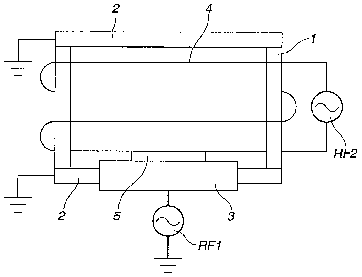
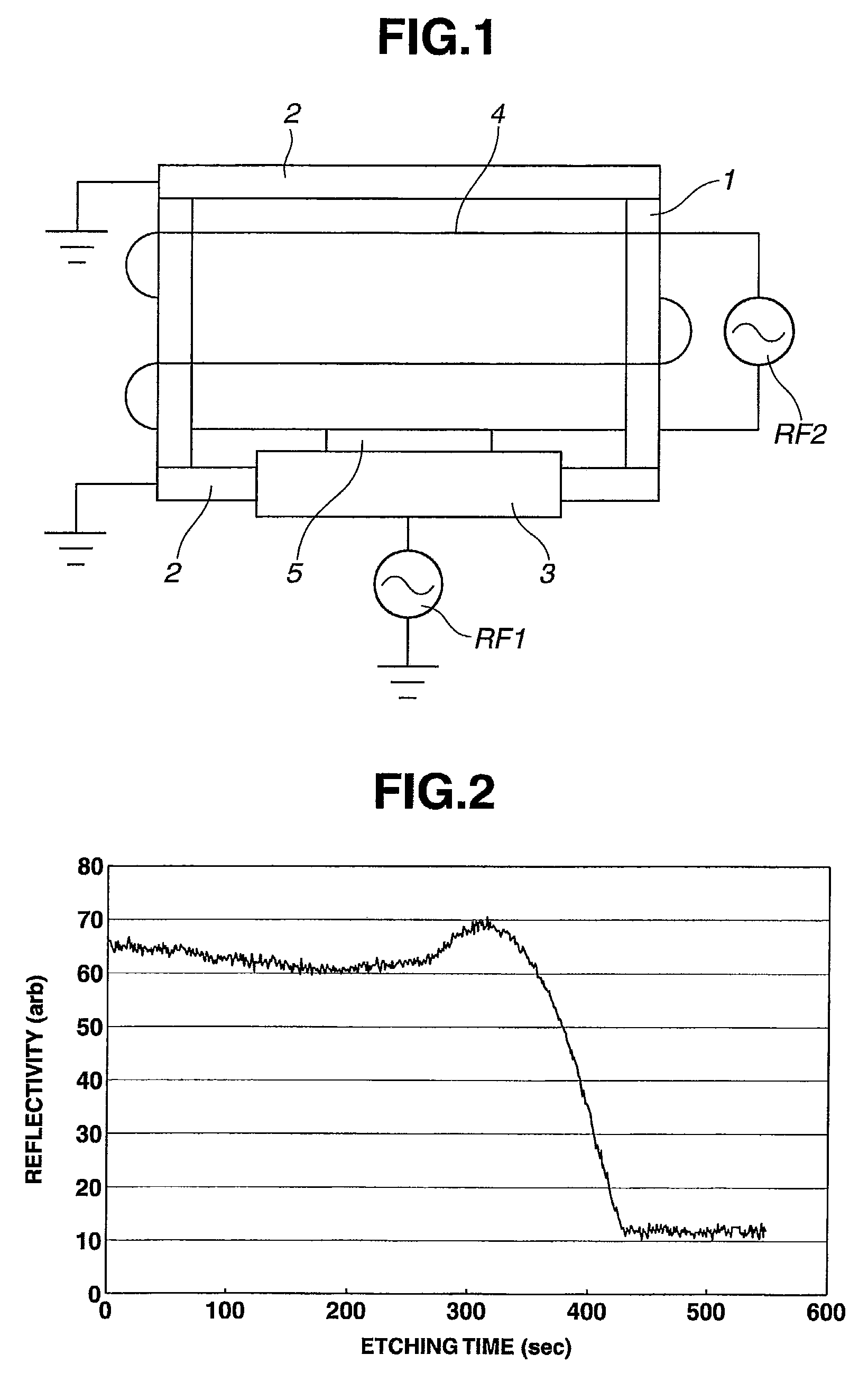
[0057]Using the etching system of FIG. 1, the light-shielding film of MoSi-based material and the etch mask film of chromium-based material thus deposited were subjected to fluorine base dry etching under seven sets of etching conditions A to G. The etching clear time was determined. The set of etching conditions is shown in Table 1.

[0058]

TABLE 1EtchingGasPowerGas flow rateconditionpressure(W)(sccm)set(mTorr)RF1RF2SF6O2HeA55432518450B5543251845130C55415018450D5543259450E51003251845130F510015018450G51003259450RF1: reactive ion etching (...


PUM

PropertyMeasurementUnit
wavelengthaaaaaaaaaa
thicknessaaaaaaaaaa
thicknessaaaaaaaaaa

Abstract

In conjunction with a photomask blank comprising a transparent substrate, a pattern-forming film, and an etch mask film, a set of etching conditions for the pattern-forming film is evaluated by measuring a first etching clear time (C1) taken when the etch mask film is etched under the etching conditions to be applied to the pattern-forming film, measuring a second etching clear time (C2) taken when the pattern-forming film is etched under the etching conditions, and computing a ratio (C1 / C2) of the first to second etching clear time.

Description

CROSS-REFERENCE TO RELATED APPLICATION[0001]This non-provisional application claims priority under 35 U.S.C. §119(a) on Patent Application No. 2011-252970 filed in Japan on Nov. 18, 2011, the entire contents of which are hereby incorporated by reference.TECHNICAL FIELD[0002]This invention relates to a method of evaluating a set of etching conditions for a pattern-forming film of a photomask blank which is processed to form a photomask for use in the micro-fabrication of semiconductor integrated circuits, charge-coupled devices (CCD), liquid crystal display (LCD) color filters, and magnetic heads. More particularly, in conjunction with a photomask blank comprising a pattern-forming film and an etch mask film, the invention relates to a method of evaluating a set of etching conditions for the pattern-forming film.BACKGROUND ART[0003]In the recent semiconductor processing technology, a challenge to higher integration of large-scale integrated circuits places an increasing demand for mi...

Claims


Application Information

Patent Timeline
Patent Type & Authority Patents(United States)
IPC IPC(8): C03C15/00G16Z99/00G03F1/00G03F1/26G03F1/80
CPCG06F19/00G03F1/26G03F1/80G03F1/0046G16Z99/00G03F1/44H01L21/0274H01L22/26H01L22/30
Inventor IGARASHI, SHINICHIYOSHIKAWA, HIROKIINAZUKI, YUKIOKANEKO, HIDEO
Owner SHIN ETSU CHEM CO LTD
Learn More