Method and system for controlling gait of robot

a technology of wearable robots and gaits, applied in the direction of electric programme control, program control, instruments, etc., can solve the problems of difficult difficult to actively and variably control the robot, and inability to precisely determine the intended gait of the wearer, etc., to achieve the effect of reducing production costs, reducing load and comfortable wearing sensation

Active Publication Date: 2015-03-31
HYUNDAI MOTOR CO LTD
View PDF31 Cites 4 Cited by
  • Summary
  • Abstract
  • Description
  • Claims
  • Application Information

AI Technical Summary

Benefits of technology

[0013]An object of the present disclosure is to provide a method and system for controlling the gait of a wearable robot based on a walking speed and an intended gait of a wearer.
[0022]As described above, a method and system for controlling the gait of a robot according to the present disclosure provides a control algorithm which may reduce a load based on an imaginary reaction force using, e.g., On / Off switches of a foot module so that an inexpensive sensor can be used without needing an expensive F / T sensor. Thereby, the production cost can be reduced. In addition, the present disclosure can more precisely sense the intended gait of the wearer and control the robot.
[0023]Furthermore, a method in which the walking speed of the wearer can be calculated using a digital flow of the On / Off switches can avoid the problem of the conventional intention sensing method having low reliability due to chattering and noise of the F / T sensor. Therefore, the present disclosure can provide a comfortable wearing sensation to the wearer.

Problems solved by technology

When a wearer who is wearing a robot walks, if the robot does not correctly reflect the intended gait of the wearer, the wearer will feel a load from the robot, and the load will be manifested as instability while the wearer is walking.
However, such a method requires measures to be implemented that solve problems induced by a chattering phenomenon and noise generation of the sensor when the wearer is walking.
Further, the sensor is very expensive, and an additional amplifier circuit and signal processing board are required.
However, when using the above-mentioned conventional method, it is very difficult to precisely determine the intended gait of the wearer and to actively and variably control the robot.
Furthermore, the number of sensors is relatively large, thereby increasing the production cost.

Method used


Image

  • Method and system for controlling gait of robot
  • Method and system for controlling gait of robot
  • Method and system for controlling gait of robot

Examples


Embodiment Construction

[0030]Hereinafter, a method and system for controlling the gait of a robot according to a preferred embodiment of the present disclosure will be described in detail with reference to the attached drawings.

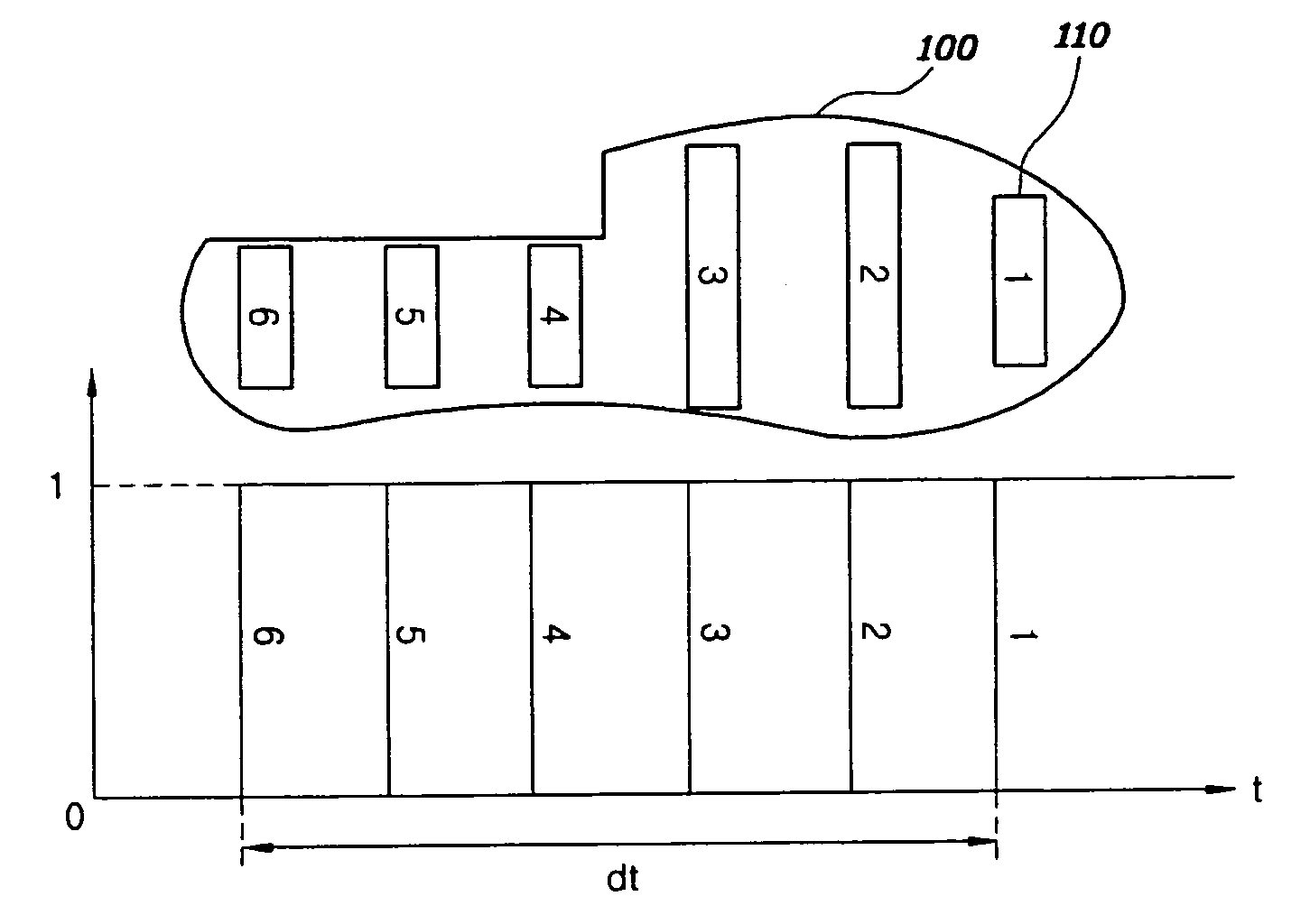
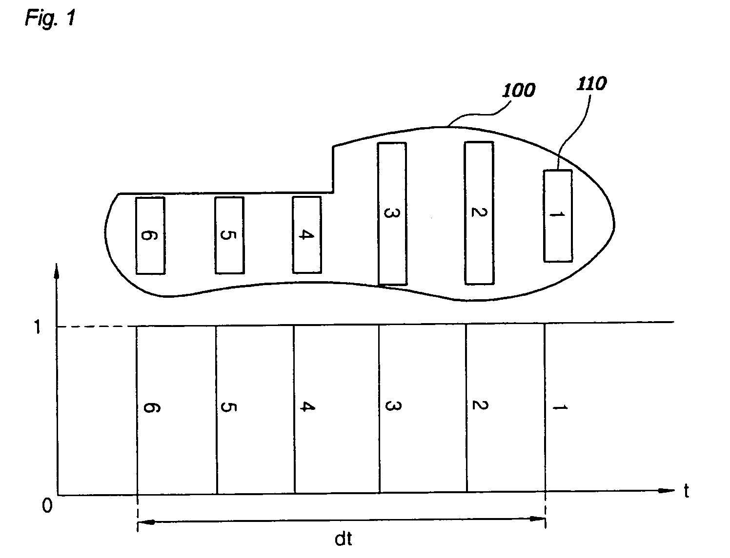
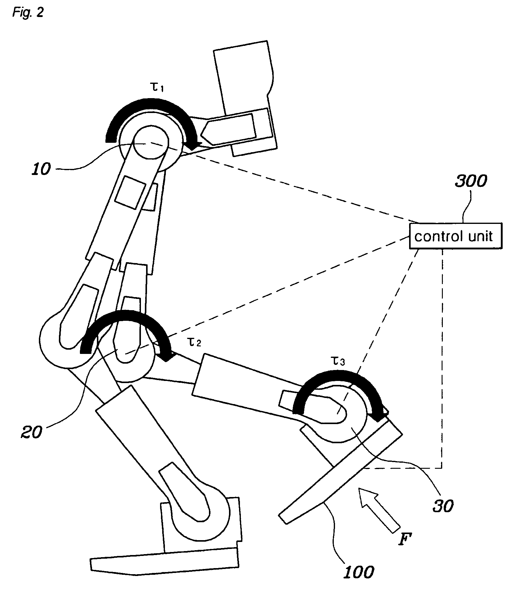
[0031]FIG. 1 is a view illustrating surface contact sensors used in a method for controlling the gait of a robot, according to an exemplary embodiment of the present disclosure. FIG. 2 is a view illustrating construction of a system for controlling the gait of a robot, according to an exemplary embodiment of the present disclosure. FIG. 3 is a flowchart of an exemplary robot gait control method according to the present disclosure. FIG. 4 is a graph showing a trigonometric function of the robot gait control method according to the present disclosure.

[0032]FIG. 3 is a flowchart of an exemplary robot gait control method according to the present disclosure. The robot gait control method includes a determination step S100 of determining whether the robot is in a walking state and determ...


PUM


Abstract

A method includes determining whether a robot is walking and a direction in which the robot is walking; measuring an amount of time taken for a sole of a foot of the robot to step on the ground; calculating an imaginary reaction force applied to the sole using a trigonometric function having, as a period, the measured amount of time taken for the sole to step on the ground; and applying the calculated imaginary reaction force to a Jacobian transposed matrix and converting the imaginary reaction force into a drive torque for a lower extremity joint of the robot.

Description

BACKGROUND OF THE DISCLOSURE[0001]1. Field of the Disclosure[0002]The present disclosure relates to a method and system for controlling the gait of a wearable robot based on a walking speed of a wearer and the intended gait of the wearer.[0003]2. Description of the Related Art[0004]The present disclosure relates to a gait control algorithm for reducing a load of a wearable walking robot. When a wearer who is wearing a robot walks, if the robot does not correctly reflect the intended gait of the wearer, the wearer will feel a load from the robot, and the load will be manifested as instability while the wearer is walking.[0005]To overcome the above problem, the present disclosure provides a control algorithm which determines a speed at which the wearer intends to walk, and provides an imaginary reaction force corresponding to the intended movement of a foot that is being swung, thus reducing the load generated by the robot.[0006]Existing wearable robots mainly use a force / torque senso...

Claims


Application Information

Patent Timeline
Patent Type & Authority Patents(United States)
IPC IPC(8): B25J5/00B25J9/16
CPCB25J9/1607Y10S901/01B25J13/081B62D57/032B25J13/08B25J17/00B25J19/06
Inventor LEE, SEOK WONYANG, WOO SUNG
Owner HYUNDAI MOTOR CO LTD
Why Eureka
Try Eureka