System and method for providing improved display quality by display adjustment and image processing using optical feedback

a technology of optical feedback and display adjustment, applied in the field of graphical displays, can solve the problems of not having to have very high-quality displays, the eye does not realize the beam is being rasterized, and neither the many papers they refer to actually contemplate changing the coarse parameters, so as to achieve coarse control of display behavior and display further improve

Active Publication Date: 2015-03-31
SCALABLE DISPLAY TECH
View PDF30 Cites 17 Cited by
  • Summary
  • Abstract
  • Description
  • Claims
  • Application Information

AI Technical Summary

Benefits of technology

[0011]This invention overcomes disadvantages of the prior art by providing an improved display system and method that is created by adjusting the properties of one or more displays to obtain coarse control over display behavior, by using sensors to optimize display parameters. The display is further improved by constructing a display map by selectively driving the display and sensing the optical image created. Furthermore, the sensors are used to ensure that the resulting optimized display meets target quality measurements over time, potentially taking into account ambient conditions. Additionally, the system reports on its status, and is able to predict when the system will no longer meet a quality target.
[0012]Taken as a whole, the illustrative system and method is able to optimize a display system and keep it optimized over time. Individual displays with the display system can have operating points that are matched to each other. Corrections to the input image signal to deliver improved display system performance can be minimized, and therefore, the unwanted artifacts of those changes can be minimized. Further, if the displays drift over time, those operating points can be updated. If ambient conditions change, and new operating points are desired, the new operating points can be automatically selected. Operators of the display who require a minimum level of quality for the display system (e.g. a minimum intensity level) can be ensured that the display meets those requirements. And, they can be warned in advance as to when system maintenance can be necessary, when quality falls below targeted goals.
[0013]In an illustrative embodiment the system and method provides for automatically modifying both the input signal to the display system (using the pixel correction function), and modifying the operating point of the display (using the display quality correction function to change the display's variable OMTE parameters). Taken together, the display system can optimize a measure of quality, while minimizing the artifacts that can be caused by modifying the input signal to a display (such as reduced dynamic range and re-sampling artifacts).
[0015]The illustrative system and method also provides for redundancy. The sensors can detect when one display in a plurality of displays is functioning poorly and turning-on another display to replace, largely replace, or augment the poorly performing display. The system and method further provides for using sensors to match the operating points (OMTE parameters / display correction function) of each display in a plurality of displays that are ganged together. Thus, rather than having each display calibrated to a standard—as can happen in a factory—the displays are calibrated to each other, making a display system that has higher quality than displays calibrated separately.
[0019]The system and method additionally provides the ability of to reduce the artifacts incurred by modifying the input signal to a display system. It does so by using the display quality correction function. It further allows the reduction of artifacts by allowing a spatial varying pixel correction function. As an example of why this is desirable, consider a ganged plurality of projectors where one region of the system is showing text. The effects of re-sampling text in the pixel correction function can be unacceptable, so it can be desirable to avoid re-sampling in a particular region. Alternatively, a sharpening filter in that region can improve the quality of the text.

Problems solved by technology

While the computational power necessary to make these systems a reality is widely available today, the required very high-quality displays are not.
If the movement of the light is sufficiently rapid, then the eye does not realize that a beam is being rasterized.
All these displays exhibit different kinds of in-factory and post-factory-introduced defects.
However, neither they nor any of the many papers they reference actually contemplate changing the coarse parameters accessible in the projector, such as contrast, brightness and lens shift.
Furthermore, when many displays are ganged together, their gross settings are generally not changed to be consistent with each other.
Current systems exhibit numerous disadvantages and operational challenges.
The modification of the input signal causes unwanted artifacts, such as resampling artifacts, or a decrease in the dynamic range of the system.
Additionally, ambient changes, such as light falling on the display, may render a brighter display system more desirable, even while permitting reduced color accuracy.

Method used


Image

  • System and method for providing improved display quality by display adjustment and image processing using optical feedback
  • System and method for providing improved display quality by display adjustment and image processing using optical feedback
  • System and method for providing improved display quality by display adjustment and image processing using optical feedback

Examples


Embodiment Construction

[0032]A. Sensors

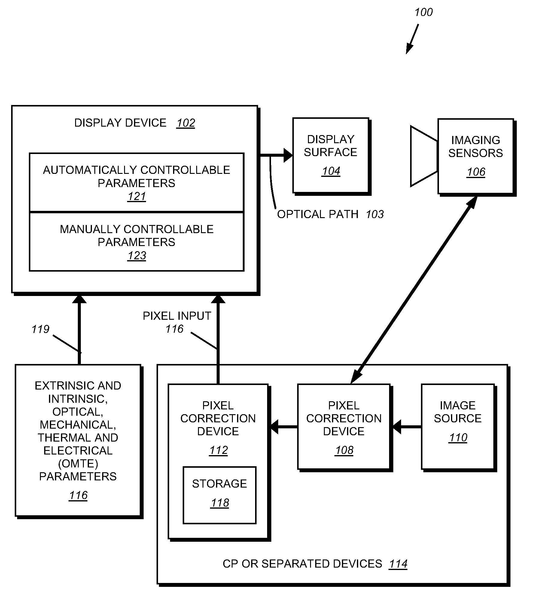
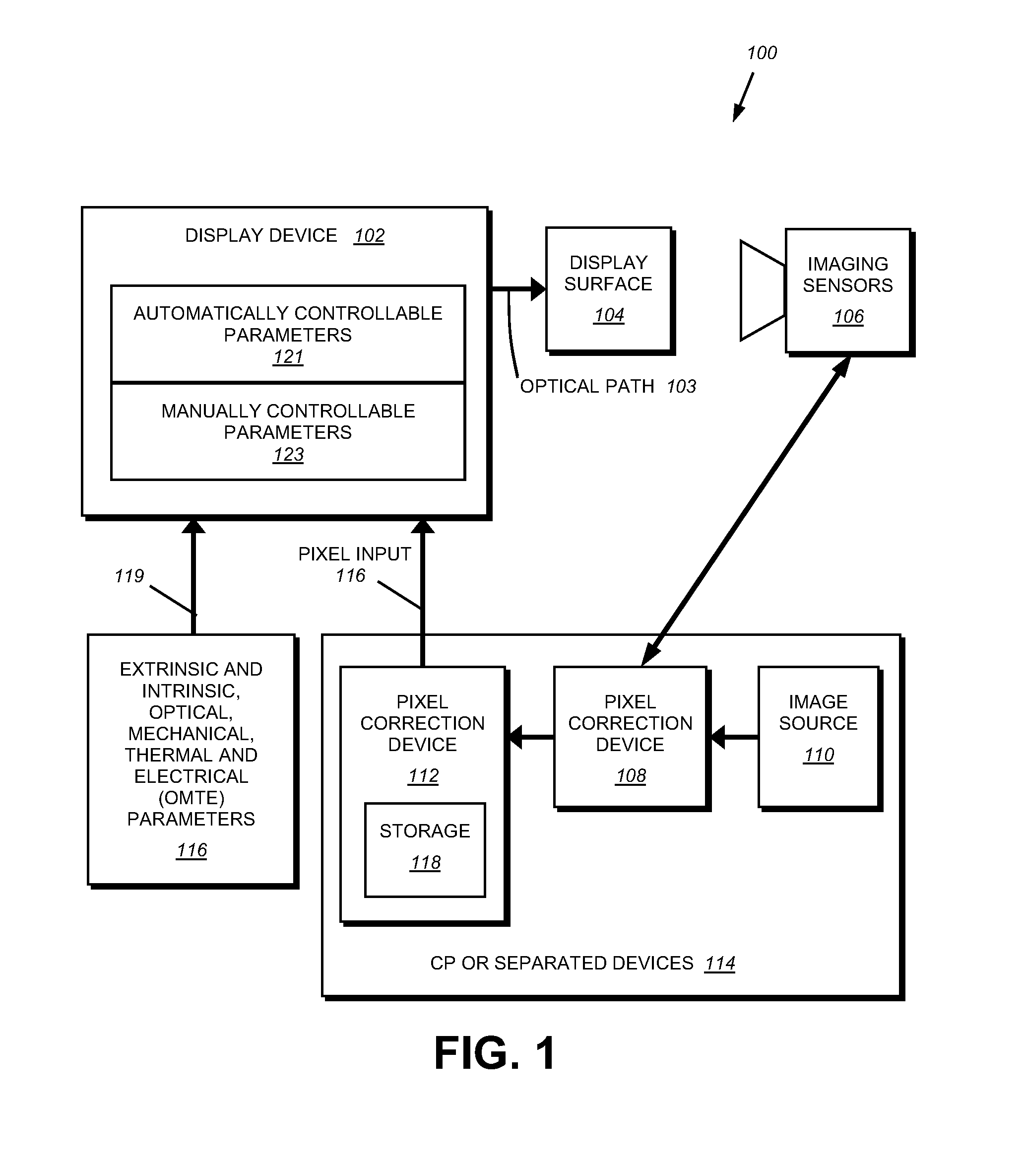
[0033]By way of further background, to capture information as to the quality of the image, the system of this invention utilizes one or more light sensors. A sensor can be defined in a variety of ways and can be one of many different types, including cameras, linear arrays of light sensors, and light sensors with no inherent spatial information, such as a photo-diode. Sometimes the system requires many sensors, and sometimes it requires only one. The sensor(s) may detect infrared, ultraviolet, or visible light in either narrow or broad-wavelength bands. It / they may be sensitive to position, as an imaging camera, or insensitive to position, as a single light level sensing photodiode. Some sensors, like camera(s), may provide a sense of the three-dimensional geometry of the system.

[0034]Note that even very simple light sensors provide significant amounts of information when used in conjunction with displays / projectors, including color, intensity and spatial information...


PUM


Abstract

A display system and method created by adjusting the properties of one or more displays to obtain coarse control over display behavior, by using sensors to optimize display parameters and meet a quality target. The display may construct a display map by selectively driving the display and sensing the optical image created. The system reports on its status, and is able to predict when the system will no longer meet a quality target. The system and method may optimize a display system and keep it optimized over time. Operators of the display who require a minimum level of quality for the display system can be ensured that the display meets those requirements. And, they can be warned in advance as to when system maintenance can be necessary, when quality falls below targeted goals system and method provides for sending out methods of the quality of the system.

Description

RELATED APPLICATION[0001]This invention claims the benefit of U.S. Provisional Application Ser. No. 60 / 895,070, entitled SYSTEM AND METHOD FOR PROVIDING IMPROVED DISPLAY QUALITY BY PROJECTOR ADJUSTMENT AND COMPUTERIZED GRAPHICAL PROCESSING USING OPTICAL FEEDBACK, by Rajeev J. Surati, et al, the teachings of which are expressly incorporated herein by reference.FIELD OF THE INVENTION[0002]This invention is related to graphical displays and more particularly to improvements in image quality in one or more displays.BACKGROUND OF THE INVENTION[0003]People love to see dynamic imagery all around them. The bigger, the brighter, the higher resolution, and the more inexpensive these displays are, the better. Today this translates to digital cinema and immersive virtual reality systems that provide a realistic visual experience. While the computational power necessary to make these systems a reality is widely available today, the required very high-quality displays are not.[0004]A display gene...

Claims


Application Information

Patent Timeline
Patent Type & Authority Patents(United States)
IPC IPC(8): G09G5/10H04N5/74
CPCH04N5/74H04N9/3147G09G3/20H04N9/3182H04N9/3194
Inventor SURATI, RAJEEV J.TIMONER, SAMSONAMARATUNGA, KEVINKNIGHT, THOMAS F.
Owner SCALABLE DISPLAY TECH
Why Eureka
Try Eureka