Controlled architecture for transport systems

a technology of control architecture and transport system, applied in the direction of digital data processing details, transportation and packaging, instruments, etc., can solve the problems of increasing the training time of operators, reducing the efficiency increasing the complexity and cost of the overall operation,

a technology of control architecture and transport system, applied in the direction of digital data processing details, transportation and packaging, instruments, etc., can solve the problems of increasing the training time of operators, reducing the efficiency increasing the complexity and cost of the overall operation,

US8996161B2Active Publication Date: 2015-03-31ROCKWELL AUTOMATION

Image

  • Controlled architecture for transport systems
  • Controlled architecture for transport systems
  • Controlled architecture for transport systems

Examples


Embodiment Construction

[0036]The present invention relates to control architecture for transport systems for receiving articles at one location and transporting the articles to another location. In describing the preferred embodiments of the invention illustrated in the drawings, specific terminology will be resorted to for the sake of clarity. However, the invention is not intended to be limited to the specific terms so selected, and it is to be understood that each specific term includes all technical equivalents that operate in a similar manner to accomplish a similar purpose.

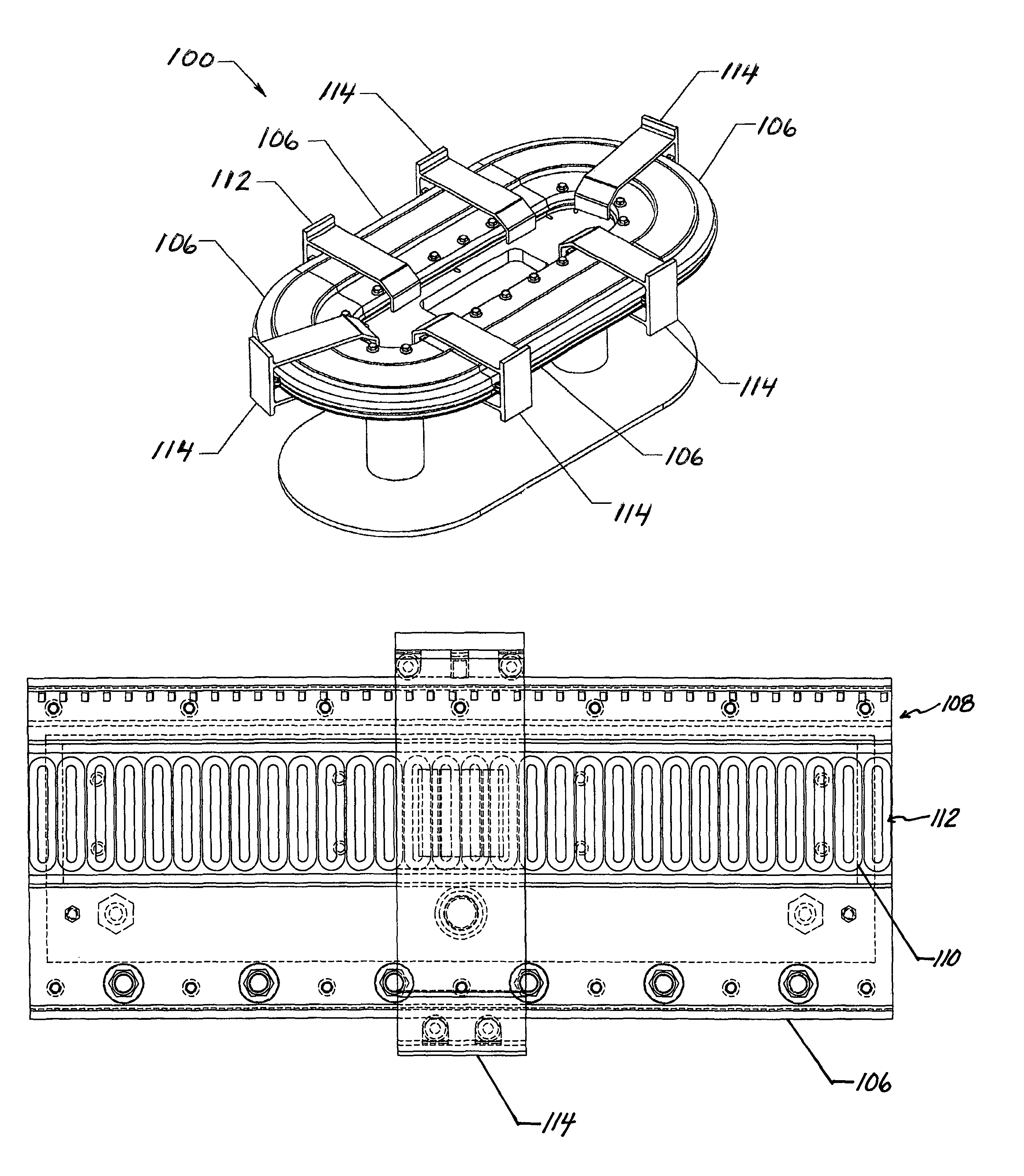
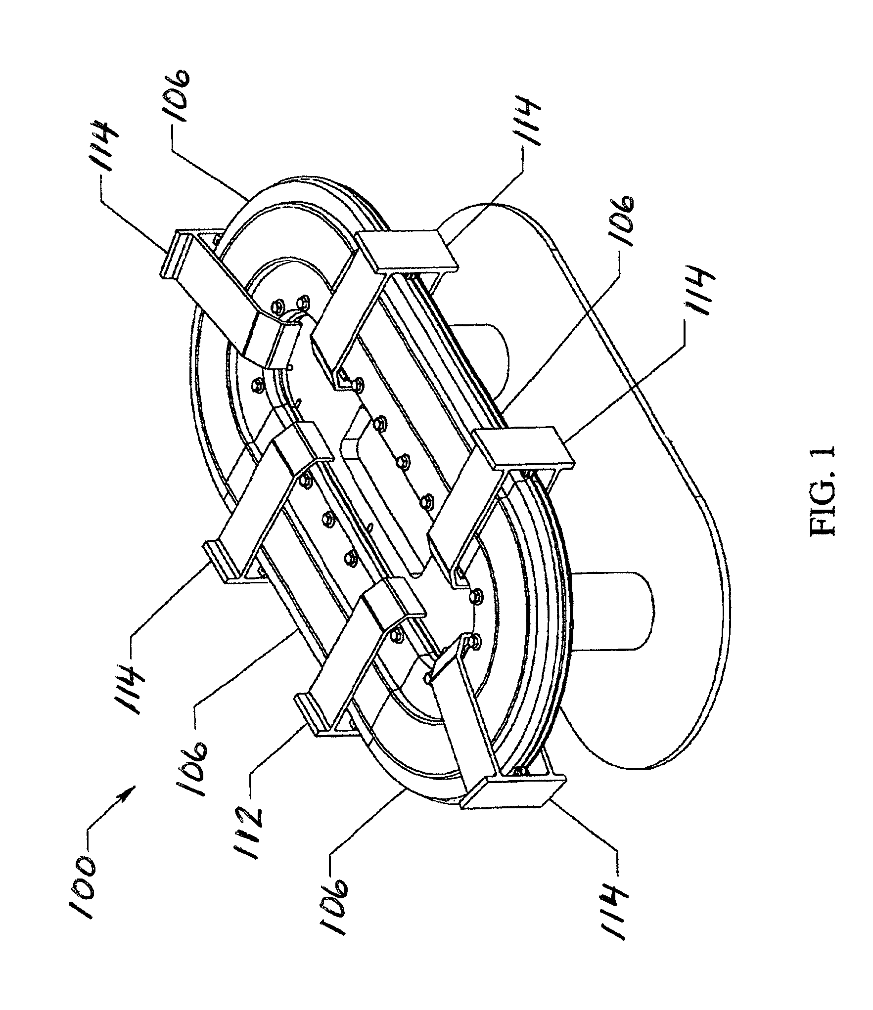
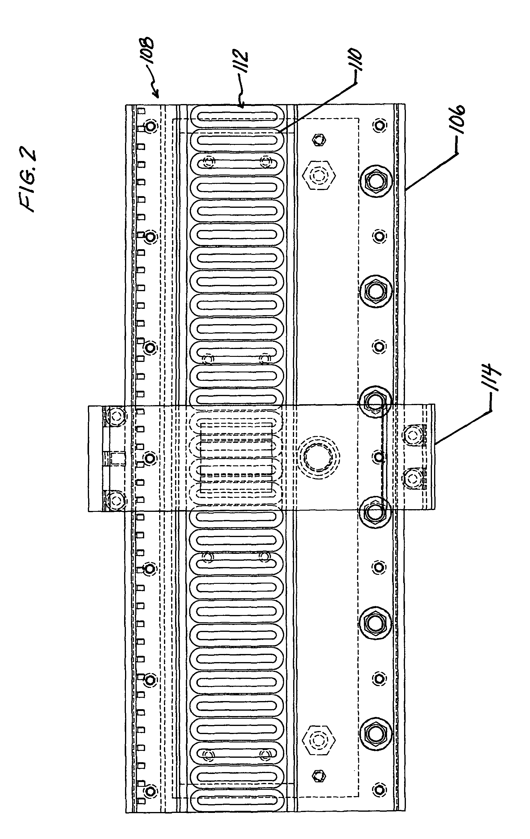
[0037]Referring to FIGS. 1, 2 and 3, a schematic representation of typical transport system 100 for moving articles from one location to another location having a preferred embodiment of the control architecture of the subject invention 102 is shown (FIG. 4). In a preferred embodiment of the invention the transport system 100 is a linear magnetic drive system preferably includes a track 104 formed from interconnected track section...


PUM


Abstract

Control architecture for use with transport systems, such as linear drive systems, rotary drive systems, or a combination thereof, comprising a computer system having a controller for operating control system software for receiving input commands and protocols for creating a motion profile for each transport element, and a gateway for receiving the motion profile from the control system software and for operating gateway drive software that functions to select the appropriate drives to move each transport element along one or more tracks in accordance with their motion profiles.

Description

CROSS-REFERENCE TO PRIOR APPLICATION[0001]This patent application relates to and claims benefit to U.S. Provisional Patent Application Ser. No. 61 / 488,012, filed May 19, 2011.TECHNICAL FIELD[0002]The present invention is directed to control architecture and, more particularly, to control architecture for use with transport systems for moving articles from one location to another location.BACKGROUND OF THE INVENTION[0003]Conventional transport systems used in industry for moving articles from one location to another typically comprise rotary dive systems having mechanical components such as gears, shafts, keys, sprockets, chains and belts, rollers, and the like for moving an axis or transport element (such as a conveyor belt) that transports articles along a predetermined path or track. The rotary drives are controlled using a computer control system that operates control software to permit an operator to enter into the control system various command parameters that are used to creat...

Claims


Application Information

Patent Timeline
31 Mar 2015
Publication
US8996161B2
IPC
G06F7/00; B61L27/04
CPC
B61L27/04; B61L2210/04; B60L15/38; B60L2200/26; B60L15/005; B60L2200/40; B60L5/32; B65G1/137
Inventors
WERNERSBACH, GLEN C.; JACOBS, KEITH G.