Crimp die set

a technology of die set and die, which is applied in the direction of drilling pipes, manufacturing tools, shaping tools, etc., can solve the problems of time-consuming, lost ground fault protection, and difficult to simply squeeze a connector onto the smooth surface and expect it to remain adhered even under minimal stress,

Active Publication Date: 2015-04-07
HUBBELL INC
View PDF26 Cites 20 Cited by
  • Summary
  • Abstract
  • Description
  • Claims
  • Application Information

AI Technical Summary

Benefits of technology

[0012]According to one aspect of various embodiments of the present invention, there is provided a crimp die set that reduces inventory.
[0013]According to another aspect of various embodiments of the present invention, there is provided a crimp die set that quickens a crimping operation.

Problems solved by technology

For example, when installing electrical connectors and ground wires to metal substrates, it is particularly imperative that the materials stay connected even under stress or otherwise the ground fault protection is lost.
A problem with smooth surfaces is that it is difficult to simply squeeze a connector onto the smooth surface and expect it to remain adhered under even minimal stress.
An issue arises when an electrical inspector is inspecting a work site and needs a way to identify if the connections are complying with the UL standard by employing the correct die index.
The process of loading the crimp tool with a first die set to condition the surface of the substrate and engaging the substrate, then removing the tool from the substrate, loading a second die set, repositioning the tool and a connector / wire assembly, and then crimping the connector / wire assembly and substrate together (and leaving a visible die index number on the surface) is time consuming.
Additionally, as will be appreciated, the cost of knurling dies and separate die index dies is expensive as an installer must purchase two crimp die sets for each crimp size, thereby increasing costs and inventory.
Not only is additional time required to conduct the crimp operation in switching between the two different crimp die sets, an improper size second die set can accidentally be used, thereby resulting in a poor crimp.
Furthermore, the foregoing highlights the long-felt, yet unresolved need in the art for a crimping method that can be used more quickly and efficiently to meet the requirements for crimping operations in the field.

Method used


Image

  • Crimp die set
  • Crimp die set
  • Crimp die set

Examples


Embodiment Construction

[0029]While the present invention will be described in connection with embodiments suited for the operation of crimping copper electrical connectors and wires to steel substrates using a hand-operated, hydraulic crimp tool, it will be readily apparent to one of ordinary skill in the art armed with the present specification that the present invention can be modified and applied to any suitable crimping operating or the like in any suitable environment.

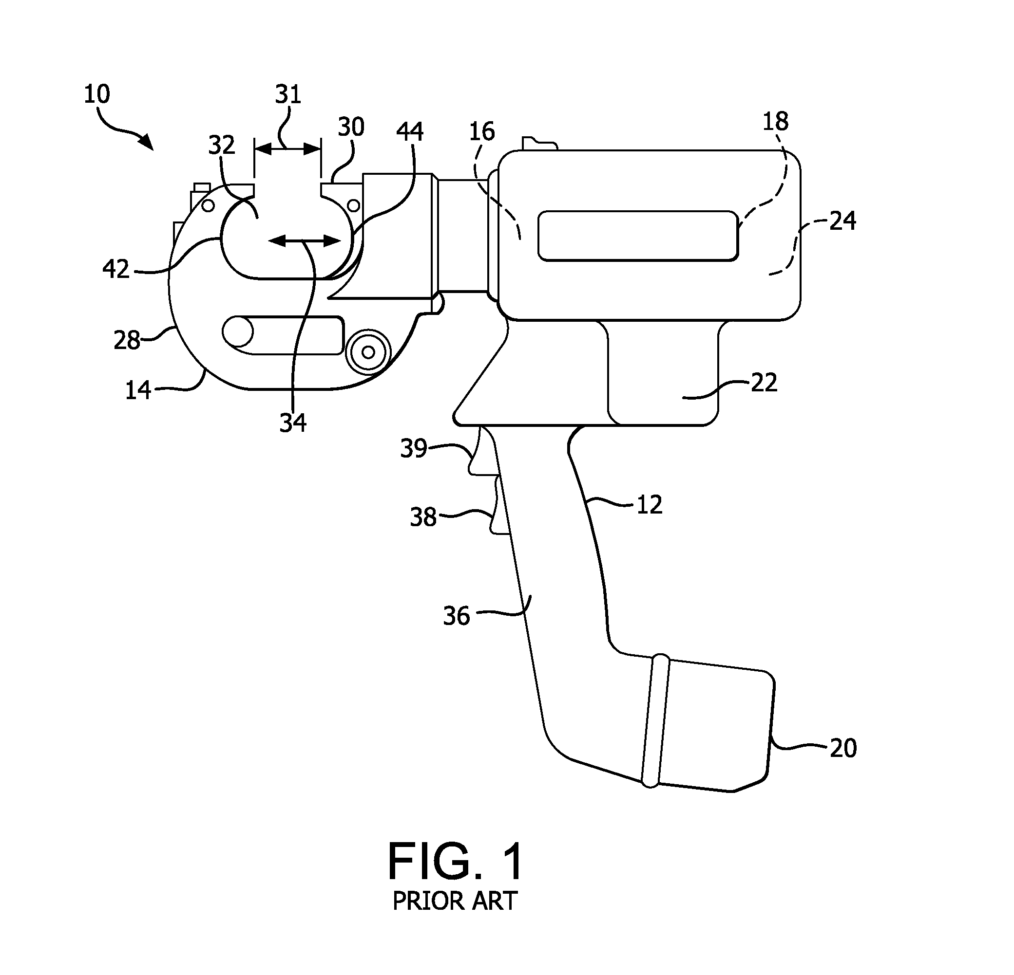
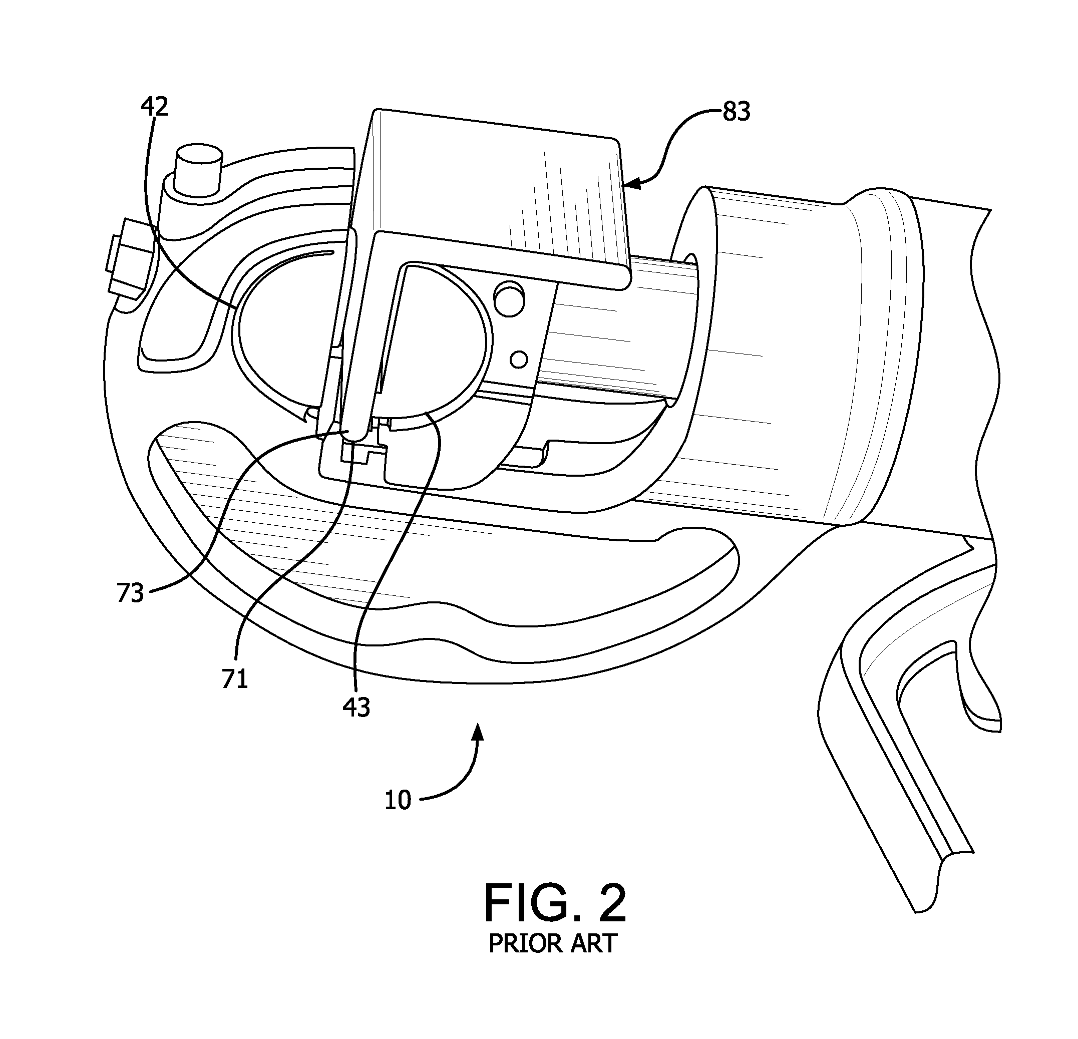
[0030]For context, a crimp tool and crimping dies commonly used in installing electrical connectors is depicted in FIGS. 1-3. As shown in FIG. 1, a conventional crimping tool 10 includes a frame 12, a working head 14, a pump 16, a motor 18, a battery 20, a fluid reservoir 22 and a controller 24. The tool can also include additional or alternative components. The frame 12 forms a ram hydraulic drive conduit system. The working head 14 comprises a frame section 28 and a ram 30. The frame section 28 is stationarily connected to the front e...


PUM

PropertyMeasurementUnit
areasaaaaaaaaaa
heightaaaaaaaaaa
lengthaaaaaaaaaa

Abstract

A die set for crimping operations includes first and second die members having raised areas including a plurality of knurls and character areas. The die set combining knurls and character areas on the operative areas of the die members allows a single die set to be used to condition a surface for crimping operations as well as crimping connectors and marking them with relevant indicia without having to change die sets.

Description

CROSS-REFERENCE TO RELATED APPLICATIONS[0001]The present application claims priority under 35 U.S.C. §119(e) to U.S. Provisional Application No. 61 / 787,449, filed Mar. 15, 2013, the contents of which are hereby incorporated by reference in their entirety.FIELD OF THE INVENTION[0002]The present invention relates generally to a crimp die set. More particularly, the present invention relates to a crimp die set having a surface including knurls and characters and methods of using the same. Still more particularly, the present invention relates to a crimp die set that prepares a surface to be crimped and embosses an identification number thereon.BACKGROUND OF THE INVENTION[0003]Crimping tools using interchangeable accessory dies are known in the art. As will be appreciated by one of ordinary skill in the art, crimp die sets are used in various fields for various purposes. One particularly applicable field involves those environments when crimping is required for grounding metal surfaces....

Claims


Application Information

Patent Timeline
Patent Type & Authority Patents(United States)
IPC IPC(8): B21D19/00E21B19/07B21D37/10
CPCB21D37/10B25B27/10H01R43/042Y02E10/50
Inventor THERRIEN, PETER N.
Owner HUBBELL INC
Why Eureka
Try Eureka