Lubrication system for a gear system providing emergency lubrication

a technology for providing lubrication and gear systems, which is applied in the direction of gear lubrication/cooling, engine lubrication, motors, etc., can solve the problem of leaving the gear system with insufficient lubrication

Active Publication Date: 2015-04-07
VESTAS WIND SYST AS
View PDF12 Cites 14 Cited by
  • Summary
  • Abstract
  • Description
  • Claims
  • Application Information

AI Technical Summary

Benefits of technology

[0005]It is an object of embodiments of the invention to provide a lubrication system for a gear system of a wind turbine, the lubrication system being adapted to switch between a normal operating mode and an emergency mode in an easy manner.
[0017]Since the vacuum generating means maintains a reduced pressure in the reservoir during normal operation as described above, the surface level of the lubricant contained in the reservoir is raised as compared to a situation where the vacuum generating means is not operating. Thereby lubricant is drawn out of the gear system and stored in the reservoir, i.e. the gear system is lubricated according to a ‘dry sump method’. This has the advantage that less friction occurs as a result of the lubrication process, thereby reducing the losses introduced in the gear system and improving the efficiency of the gear system. Furthermore, the risk of fouling the interior parts of the gear system is reduced due to the smaller amount of lubricant being present in the gear system. Finally, the temperature of the moving parts of the gear system, notably the gear teeth, is reduced, since the moving parts are not submerged in relatively hot lubricant.
[0022]The lubrication system may further comprise a valve arranged in the second fluid connection, said valve being shiftable between a first position in which a flow of lubricant is allowed between the gear system and the reservoir, via the second fluid connection and the valve, and a second position in which such a flow of lubricant is prevented. According to this embodiment, the valve may advantageously be in the first position during normal operation and in the second position during an emergency. When the valve is in the second position, the lubricant circuit described above is interrupted. A filter may be arranged in the second fluid connection, fluidly in parallel with the valve, in order to allow lubricant to flow between the reservoir and the gear system, thereby providing equalisation of the lubricant levels, in a controlled manner, and in a manner which prevents dirt and debris from passing along with the lubricant between the reservoir and the gear system.
[0026]The lubrication system may further comprise a venting connection arranged between the reservoir and the gear system. The venting connection ensures that gaseous medium, such as air, which is transferred from the reservoir is received in the gear system. Similarly, gaseous medium which is transferred from the gear system is received in the reservoir. This is an advantage because such gaseous medium may contain residues of lubricant, and the venting connection ensures that such residues of lubricant do not leave the lubrication system, i.e. it remains inside the reservoir or the gear system. Thereby lubricant loss in the system as well as pollution of the environment is minimised. Furthermore, the venting connection may be used for equalising the air pressures in the reservoir and the interior part of the gear system during emergency operation, e.g. in case of a power failure.

Problems solved by technology

However, this has the disadvantage that in the case of an emergency, possibly causing the gear system to slow down or even stop, the gear system is left with insufficient lubrication.

Method used


Image

  • Lubrication system for a gear system providing emergency lubrication
  • Lubrication system for a gear system providing emergency lubrication
  • Lubrication system for a gear system providing emergency lubrication

Examples


Embodiment Construction

[0005]It is an object of embodiments of the invention to provide a lubrication system for a gear system of a wind turbine, the lubrication system being adapted to switch between a normal operating mode and an emergency mode in an easy manner.

[0006]It is a further object of embodiments of the invention to provide a lubrication system for a gear system of a wind turbine, the lubrication system being adapted to automatically switch to an emergency mode in the case that an emergency situation is occurring.

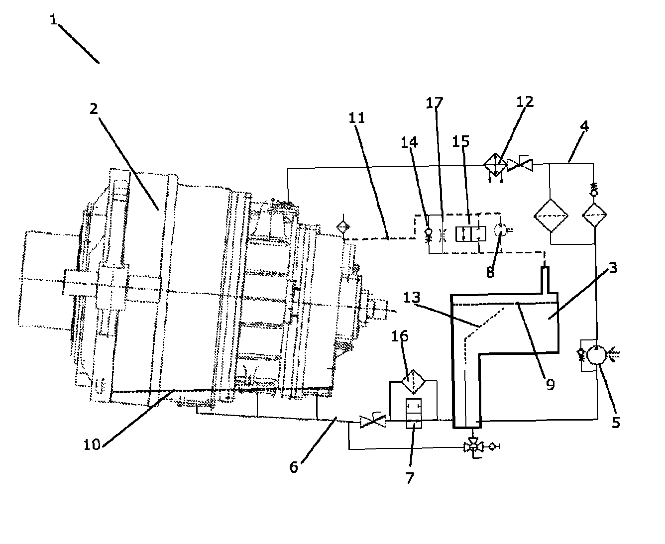
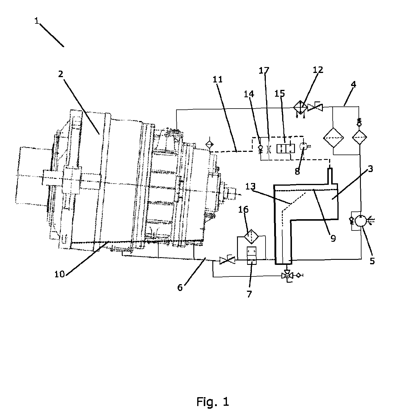
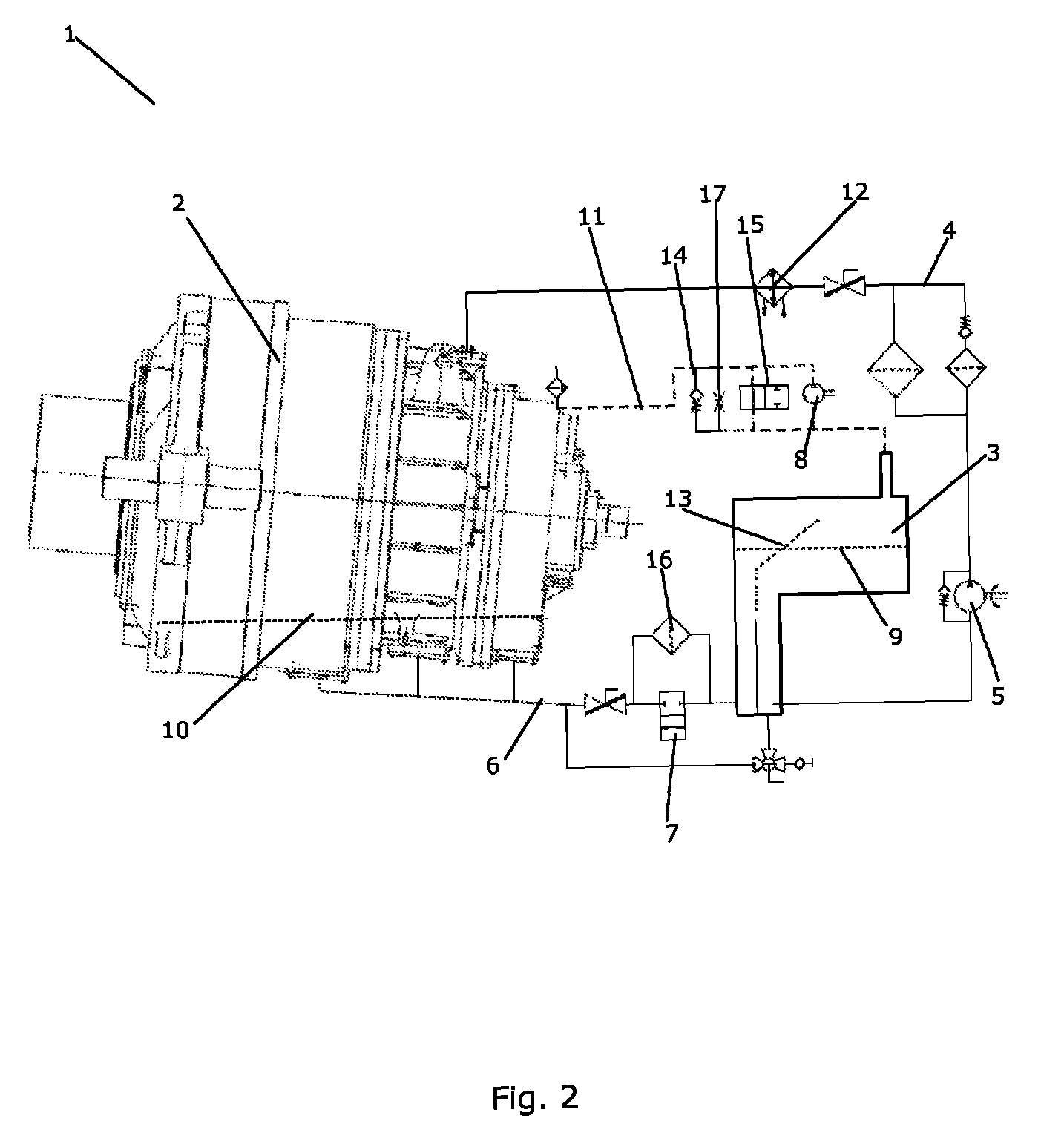
[0007]The invention provides a lubrication system for a gear system for a wind turbine, the lubrication system comprising:[0008]a reservoir adapted to contain lubricant,[0009]first pump means arranged to supply lubricant from the reservoir to the gear system via a first fluid connection, and[0010]vacuum generating means arranged in fluid connection with the reservoir, thereby maintaining a total air pressure in the reservoir which is lower than an ambient pressure during normal operati...


PUM


Abstract

A lubrication system for a gear system for a wind turbine is disclosed. The lubrication system comprises a reservoir adapted to contain lubricant, first pump means arranged to supply lubricant from the reservoir to the gear system via a first fluid connection, and vacuum generating means arranged in fluid connection with the reservoir, thereby maintaining a total air pressure in the reservoir which is lower than an ambient pressure during normal operation. The lowered total air pressure in the reservoir draws lubricant from the gear system into the reservoir, thereby increasing the lubricant level in the reservoir and decreasing the lubricant level in the gear system, allowing the lubrication system to be operated in a ‘dry sump mode’. In the case of an emergency or during start-up the vacuum generating means is stopped, thereby increasing the total air pressure in the reservoir. This causes a decrease in the lubricant level in the reservoir and an increase in the lubricant level in the gear system, allowing the lubrication system to be operated in a ‘wet sump mode’.

Description

FIELD OF THE INVENTION[0001]The present invention relates to a system for providing lubrication for a gear system of a wind turbine. More particularly, the present invention relates to a lubrication system which is operated in one state during normal operation and another state in the case that an emergency situation is occurring.BACKGROUND OF THE INVENTION[0002]Gear systems for wind turbines require lubrication during normal operation. For efficiency reasons it is sometimes desirable to provide lubrication to the gear system by means of a circulation system circulating a minimum amount of lubricant in such a manner that only an amount of lubricant necessary for lubricating the gear system during operation is present in the gear system at any time during normal operation. However, this has the disadvantage that in the case of an emergency, possibly causing the gear system to slow down or even stop, the gear system is left with insufficient lubrication. It has previously been attempt...

Claims


Application Information

Patent Timeline
Patent Type & Authority Patents(United States)
IPC IPC(8): F03D11/00F16N7/14F16H57/04
CPCF03D11/0008F16H57/0447Y02E10/722F03D80/70Y02E10/72
Inventor NIELSEN, THOMAS KORSGAARD
Owner VESTAS WIND SYST AS
Why Eureka
Try Eureka