Communication terminal apparatus and antenna device

a technology of communication terminal and antenna device, which is applied in the direction of loop antennas with ferromagnetic cores, instruments, and sensing by electromagnetic radiation, etc., can solve the problems of low space efficiency, increase in the overall size of the antenna, and increase in the size of the portable terminal apparatus, so as to achieve improved communication characteristics, significant increase in the q factor of the coil conductor, and efficient generation

Active Publication Date: 2015-04-07
MURATA MFG CO LTD
View PDF32 Cites 17 Cited by
  • Summary
  • Abstract
  • Description
  • Claims
  • Application Information

AI Technical Summary

Benefits of technology

[0008]To overcome the problems described above, preferred embodiments of the present invention provide a communication terminal apparatus and an antenna device having improved communication characteristics and in which other electronic devices can be arranged with high space efficiency.
[0011]In the antenna device described above, an induced current is generated in the coil conductor through feeding of electricity from a feeding circuit. This induced current causes an induced current to be further generated in the frame-shaped radiation conductor portion through the coupling conductor portion, and a magnetic field is generated from the frame-shaped radiation conductor portion, whereby communication with the reader / writer of an RFID system is performed. Since the booster conductor is at least partially overlapped by the coil conductor in the coupling conductor portion, an induced current is efficiently generated and communication characteristics are improved. In particular, since the radiation conductor portion of the booster conductor has a frame shape, the Q factor of the coil conductor is significantly increased, and the communication characteristics are significantly improved.
[0012]Since the radiation conductor portion of the booster conductor has a frame shape (third opening), information can be input / output through the third opening. For example, it is possible to take a photograph through the third opening by arranging a camera in the third opening, infrared communication with the outside is possible through the third opening by arranging an infrared communication apparatus in the third opening, and audio messages, for example, can be transmitted to the outside through the third opening by arranging a loud speaker in the third opening. In this manner, by arranging an electronic apparatus in the third opening to output information to the outside or receive information from the outside, high-density component mounting in a portable terminal apparatus is achieved.
[0013]According to various preferred embodiments of the present invention, communication characteristics are significantly improved and other electronic apparatuses can be arranged with high space efficiency.

Problems solved by technology

However, in this non-contact data carrier apparatus, the conductive sheet, which functions as a radiation plate, is solid and occupies a large space.
Thus, other electronic components need to be mounted in a region other than the region of the conductive sheet, which results in low space efficiency and an increase in the size of the portable terminal apparatus.
However, to obtain necessary communication characteristics, the metal surface and the antenna conductor must be increased in size, leading to an increase in the overall size of the antenna, which is also due to the thickness of the base member.
Thus, other electronic components need to be mounted in a region other than the regions of the metal surface and antenna conductor, resulting in low space efficiency and an increase in the size of the portable terminal apparatus.

Method used


Image

  • Communication terminal apparatus and antenna device
  • Communication terminal apparatus and antenna device
  • Communication terminal apparatus and antenna device

Examples


first preferred embodiment

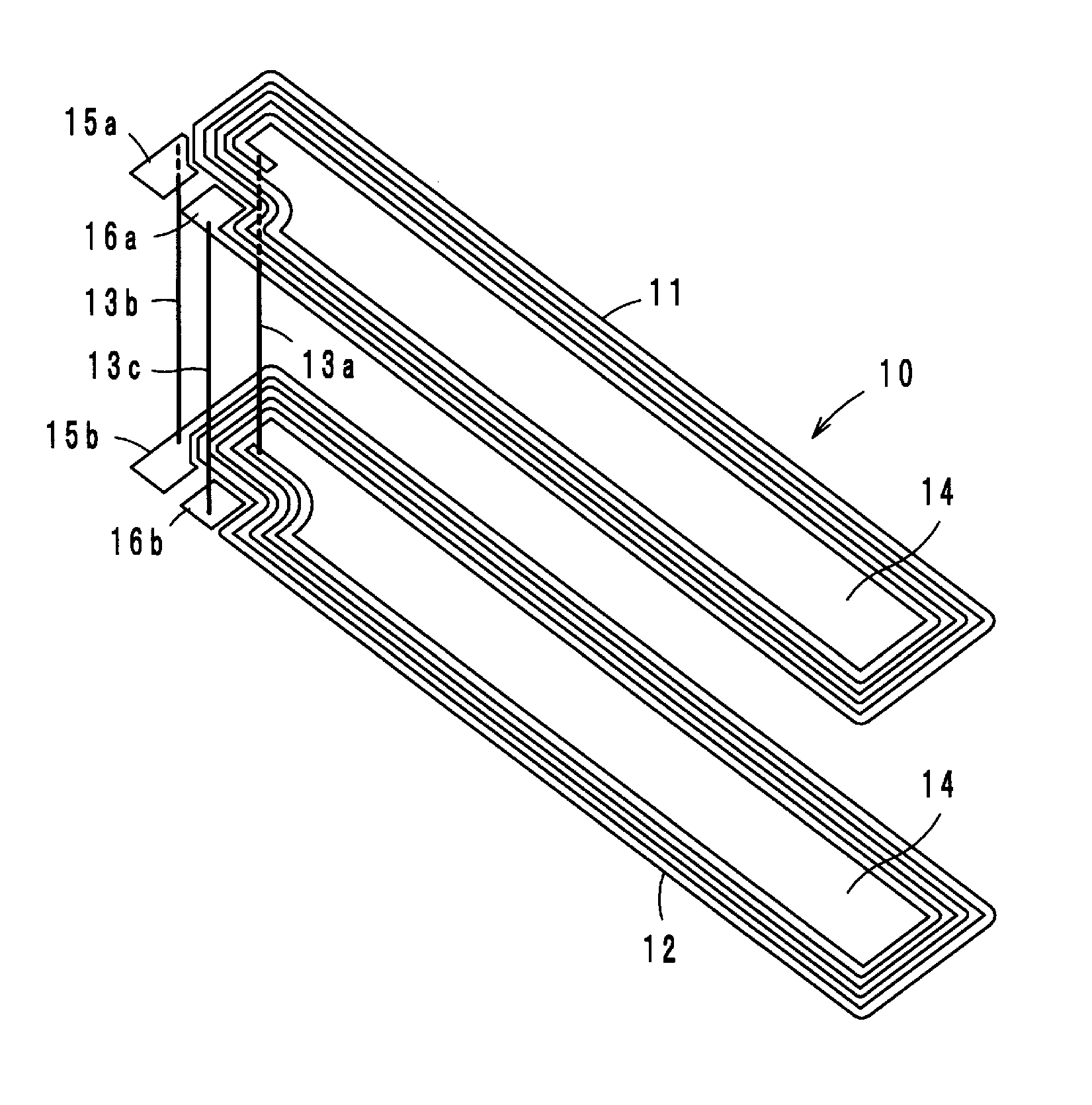
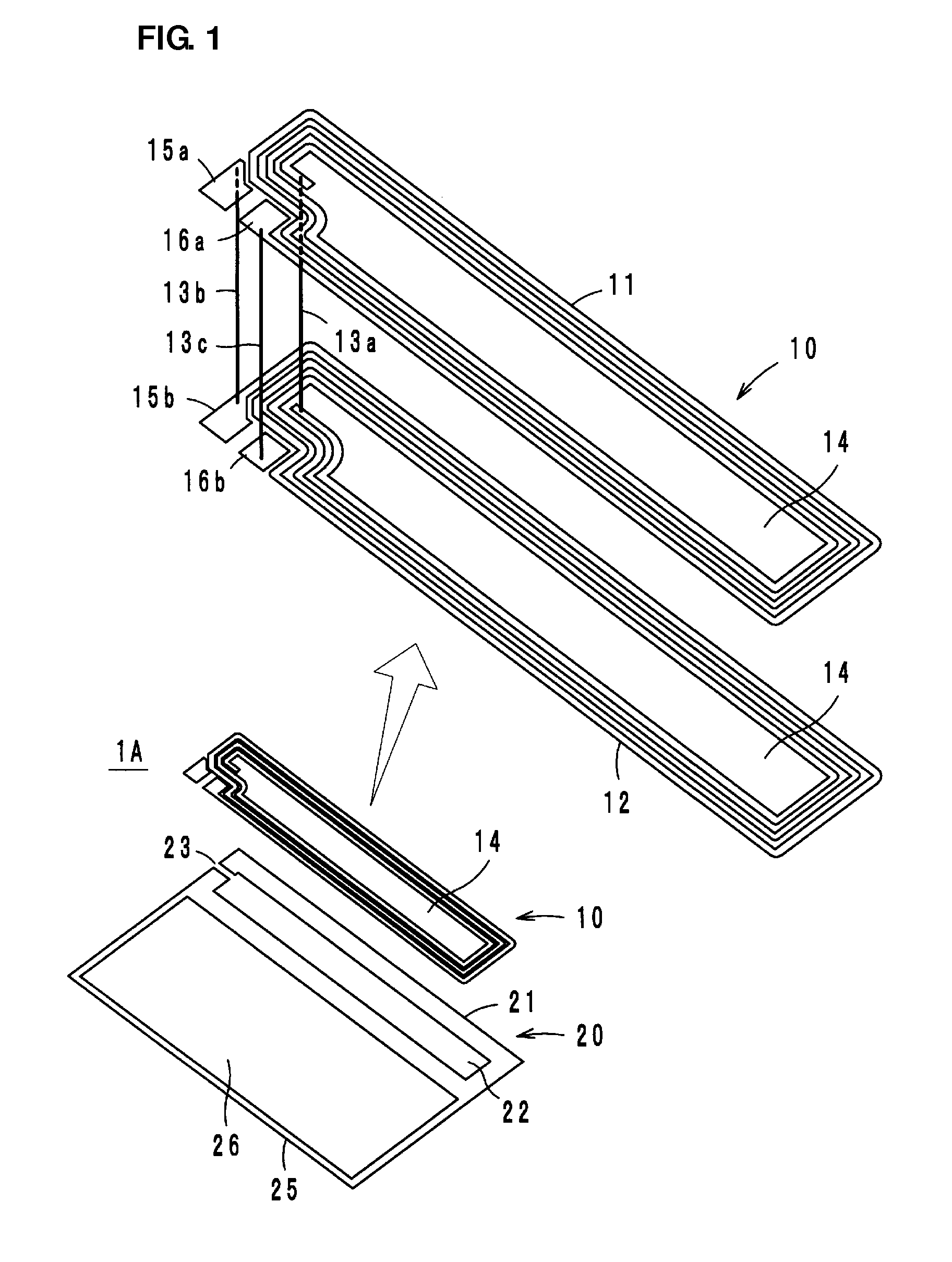
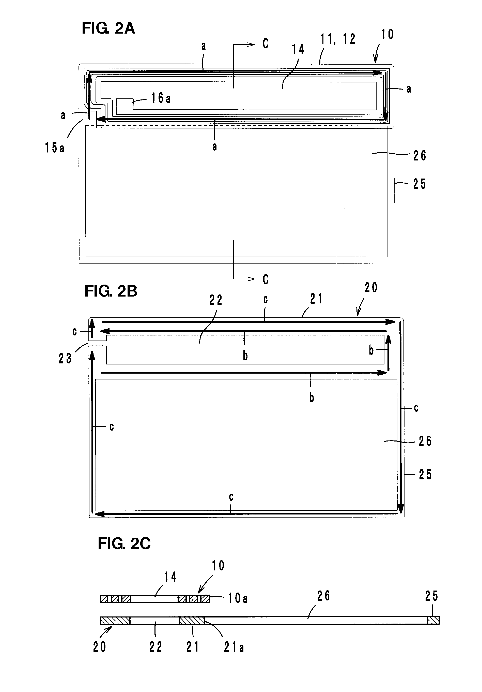
[0028]Referring to FIG. 1, an antenna device 1A according to a first preferred embodiment of the present invention includes a coil conductor 10 and a booster conductor 20. The coil conductor 10 preferably has a two-layer stacked structure including an insulating sheet, which is not illustrated in the figure, between the layers, for example. Loop-shaped conductors 11 and 12 that are wound so as to be superposed with each other in plan view are connected at ends thereof through a via hole conductor 13a, thereby forming a single coil including a first opening 14 at the center of the winding. Further, feeding terminals 15a and 15b are connected to each other through a via hole conductor 13b, and feeding terminals 16a and 16b are connected to each other through a via hole conductor 13c. The feeding terminal 15b is connected to one end of the loop-shaped conductor 12 and the feeding terminal 16a is connected to one end of the loop-shaped conductor 11. The feeding terminals 15a and 16a are...

second preferred embodiment

[0042]Referring to FIGS. 9A and 9B, an antenna device 1B according to a second preferred embodiment of the present invention preferably includes a frame-shaped radiation conductor portion 25 that is connected to two points located on a diagonal line of a square-shaped coupling conductor portion 21. A coil conductor 10 is overlaid on the coupling conductor portion 21 as a single-layer loop-shaped conductor 18 that is preferably wound in a square shape, for example. The two ends of the loop-shaped conductor 18 define feeding terminals 18a and 18b. The antenna device 1B has the same or substantially the same operations and advantages as the antenna device 1A.

third preferred embodiment

[0043]Referring to FIGS. 10A and 10B, an antenna device 1C according to a third preferred embodiment of the present invention preferably includes a coil conductor 10 and a coupling conductor portion 21 that are substantially L-shaped, for example, and are superposed with each other. The coil conductor 10 is defined by a single-layer loop-shaped conductor 18, and the two ends of the loop-shaped conductor 18 define feeding terminals 18a and 18b. The antenna device 1C also has the same or substantially the same operations and advantages as the antenna device 1A.


PUM

PropertyMeasurementUnit
resonance frequencyaaaaaaaaaa
magneticaaaaaaaaaa
electromagnetic fieldaaaaaaaaaa

Abstract

An antenna device which includes a coil conductor and a booster conductor. The coil conductor is defined by wound loop-shaped conductors and includes a first opening at a winding center and two ends connected to a feeding circuit. The booster conductor includes a coupling conductor portion and a frame-shaped radiation conductor portion. The coupling conductor portion includes a second opening overlapped at least partially by the first opening, is split in a portion thereof by a slit, and is electromagnetically coupled to the coil conductor. The frame-shaped radiation conductor portion includes a third opening and is connected to the coupling conductor portion.

Description

BACKGROUND OF THE INVENTION[0001]1. Field of the Invention[0002]The present invention relates to communication terminal apparatuses and antenna devices. In particular, the present invention relates to communication terminal apparatuses and antenna devices that can be used in a radio frequency identification (RFID) system.[0003]2. Description of the Related Art[0004]In recent years, an RFID system has been used as an article information management system. In an RFID system, predetermined information is transmitted between a reader / writer that generates an induction field and an RFID tag attached to an article, through non-contact communication based on an electromagnetic field. An RFID tag stores predetermined information and includes a wireless IC (feeding circuit) that processes a predetermined wireless signal and an antenna device that performs transmission / reception of a high-frequency signal. Further, various portable terminal apparatuses that include an antenna device for an RF...

Claims


Application Information

Patent Timeline
Patent Type & Authority Patents(United States)
IPC IPC(8): H01Q7/00G06K7/10H01F38/14H01Q1/22H01Q19/00
CPCH01F38/14G06K7/10009H01Q1/2225H01Q7/00H01Q19/00H01Q7/06
Inventor NAKANO, SHINICHIKATO, NOBORU
Owner MURATA MFG CO LTD
Why Eureka
Try Eureka