Transporting and storing container for liquids

a technology for transporting and storing containers and liquids, applied in the directions of transportation and packaging, pliable tubular containers, tray containers, etc., can solve problems such as failure of containers, and achieve the effect of reducing the cost of materials

Active Publication Date: 2015-04-14
PROTECHNA SA
View PDF13 Cites 2 Cited by
  • Summary
  • Abstract
  • Description
  • Claims
  • Application Information

AI Technical Summary

Benefits of technology

[0007]The object of the present invention is to provide a transport and storing container whose cage mantle comprises vertical bars with a bent section formed in the transition to the connection section, wherein the transport and storing container has the necessary security against component failure and can still be manufactured with a minimum of material cost.
[0010]As a result, the general possibility arises to guarantee the desired high standard against container failure for the transport and storing container even if a tube material with a relatively thin wall thickness is chosen for producing the vertical bars. Thus it can be made secure even for a tube material with a relatively thin wall thickness that a breaking of a vertical bar due to exceeding the critical buckling load can be eliminated with sufficient likelihood. Said breaking of a vertical bar, i.e. component failure of a vertical bar, could otherwise lead to a broken end of the vertical bar penetrating the plastic inner container, which would directly result in container failure.
[0011]In addition to the weight advantage provided by using a tube material with a relatively thin wall thickness, the possible reduction of production costs for a transport and storing container due to the corresponding saving of material has of course to be noted as a further substantial advantage resulting from the realization according to the invention,
[0012]It is particularly advantageous if the upper ends as well as the lower ends of the vertical bars have a convex cross-section outline in the transition from the connection section to the bent section so that the lower ends provide a higher security against component failure as well.
[0015]Due to the cross-sectional form resulting from the groove-shaped recess and compared to a vertical bar whose bent section is not equipped with a groove-shaped recess in the transition to the connection section, a rigid structure is made possible, providing a higher buckling safety, notwithstanding the desired elastic flexibility in the transition to the connection section. Herein, the effect of the groove-shaped recess can be roughly compared to the stiffening effect of a bead while having the particularity that said groove-shaped recess extends from the connection section across the bent section to the longitudinal section. Compared to vertical bars whose bent section is not equipped with such a groove-shaped recess, this structural reinforcement of the vertical bars provides even further improved buckling safety when using tube material with relatively thin wall thickness.
[0017]If, due to the recess, a kidney-shaped cross-section is formed which continuously extends with a convex wall section of the bar opposing the groove-shaped recess from the longitudinal section across the bent section into the connection section of the bar, a further increase in buckling safety in the area of the bent section and in the transition from the bent section to the connection section is achieved.

Problems solved by technology

Said breaking of a vertical bar, i.e. component failure of a vertical bar, could otherwise lead to a broken end of the vertical bar penetrating the plastic inner container, which would directly result in container failure.

Method used


Image

  • Transporting and storing container for liquids
  • Transporting and storing container for liquids
  • Transporting and storing container for liquids

Examples


Embodiment Construction

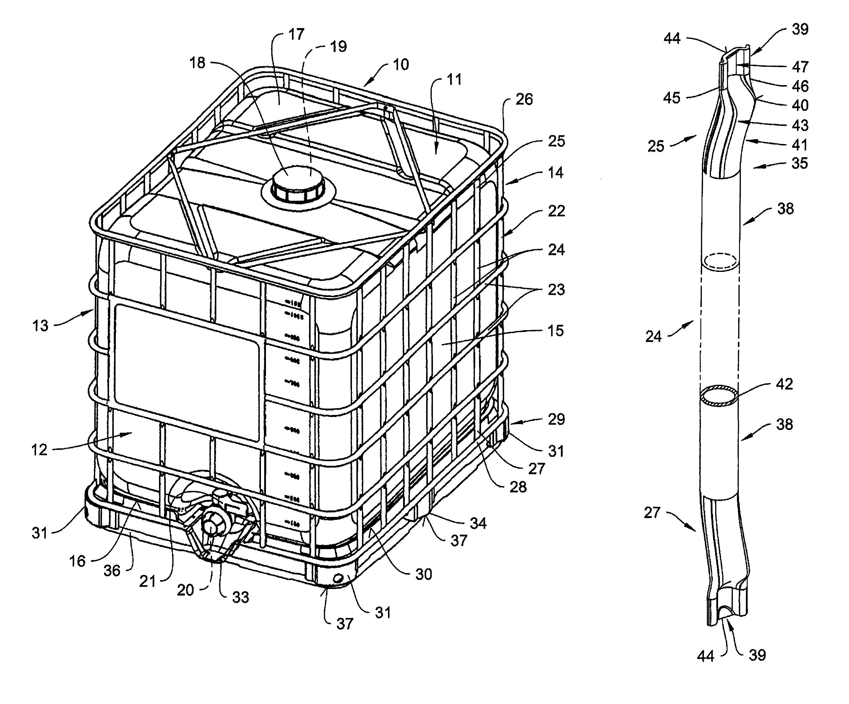
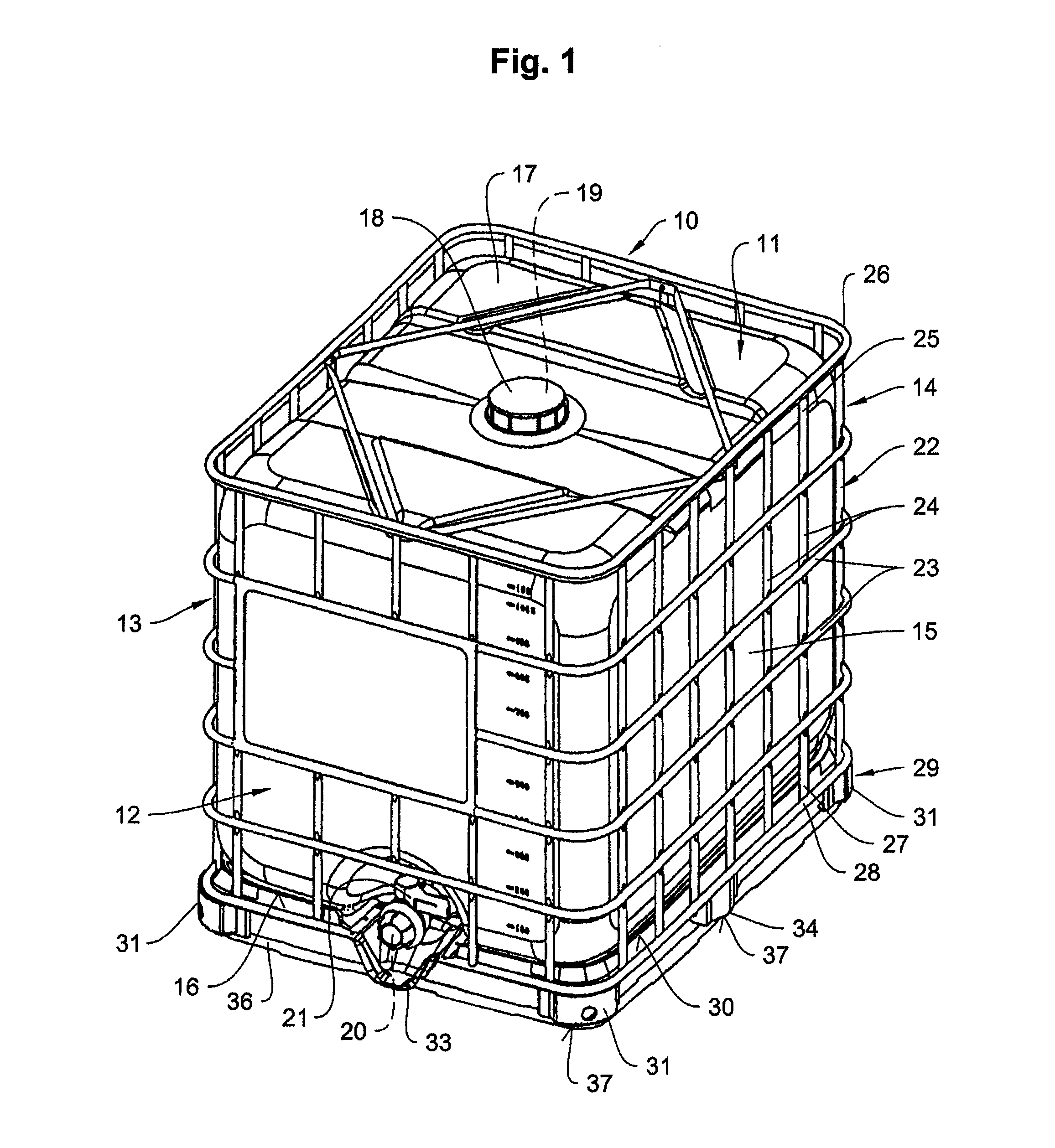
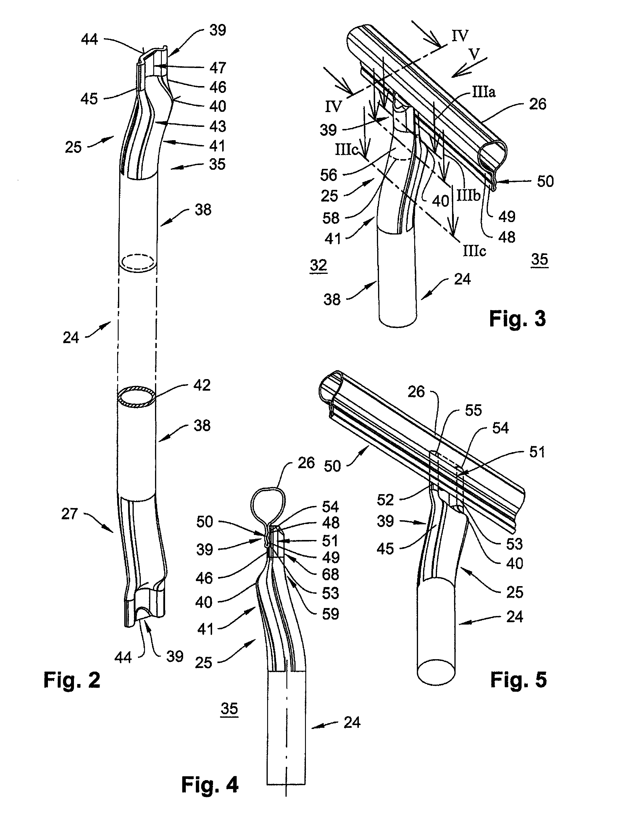
[0040]FIG. 1 shows a transport and storage container 10 for liquids, usable as a disposable or reusable container, which comprises an inner container 11 made of plastic with four side walls 12, 13, 14 and 15 and a lower and an upper bottom wall 16, 17, a filler neck 19, closable with a lid 18 and formed on the upper bottom wall 17, and a draining neck 20 with a tapping armature 21 formed on a lower section of the side wall 12, further an outer cage mantle 22 of horizontal and vertical metal bars 23, 24 crossing each other for receiving the inner container 11. The vertical bars 24 are welded with an upper end 25 to an upper edge profile 26 and with a lower end 27 to a lower edge profile 28 of the cage mantle 22. Furthermore, the cage mantle 22 is connected via its lower edge profile 28 to a pallet-type base frame 29.

[0041]The pallet-type base frame 29 comprises a bottom wall 30, on which the inner container 11 is disposed, and which is arranged on corner legs 31, a not further illust...


PUM


Abstract

A transport and storing container for liquids includes a pallet-type base frame for an inner container made of plastic with side walls, a lower wall and an upper wall. A closable filler neck is formed on the upper wall. A draining neck with a tapping armature is formed on a lower section of a side wall. A cage mantle with horizontal and vertical bars made of metal receives the inner container, wherein the vertical bars comprise between a connection section and a linear longitudinal section with a tubular cross section a bent section, and at least the upper ends of the vertical bars comprise a convex cross section outline on their inner side facing the inner container in the transition of the connection section to the bent section.

Description

CROSS REFERENCE TO RELATED APPLICATION[0001]The present application claims the benefit of German Patent Application No. 10 2011 087 927.7 filed Dec. 7, 2011, which is fully incorporated herein by reference.STATEMENT REGARDING FEDERALLY SPONSORED RESEARCH OR DEVELOPMENT[0002]Not applicable.FIELD OF THE INVENTION[0003]The present invention relates to a transport and storing container for liquids with a pallet-type base frame for an inner container made of plastic with four side walls, a lower and an upper bottom wall, a closable filler neck formed on the upper bottom wall, a draining neck with a tapping armature formed on a lower section of a side wall, and a cage mantle with horizontal and vertical bars made of metal for receiving the inner container, wherein the ends of the vertical bars formed as hollow profiles are welded to a lower and an upper circumferential edge profile of the cage mantle, wherein at least the upper edge profile comprises a ridge running crosswise to the verti...

Claims


Application Information

Patent Timeline
Patent Type & Authority Patents(United States)
IPC IPC(8): B65D8/08B65D25/20B65D77/04
CPCB65D25/20B65D77/0466B65D88/10B65D88/20
Inventor SCHUTZ, UDO
Owner PROTECHNA SA
Why Eureka
Try Eureka