
System for connecting housing elements of a device for heat transfer

a technology of heat transfer and housing elements, which is applied in the direction of indirect heat exchangers, machines/engines, lighting and heating apparatus, etc., can solve the problems of reducing the utilisation of interior installation space, increasing the risk of undesirable latching connection, and reducing the efficiency of the installation process, so as to achieve maximum resistance to fatigue and destruction of the connection, the effect of reducing the cost of manufacturing and material costs

Active Publication Date: 2021-03-23
HANON SYST
View PDF27 Cites 0 Cited by
  • Summary
  • Abstract
  • Description
  • Claims
  • Application Information

AI Technical Summary

Benefits of technology

The invention is about improving the connection between housing elements of a device for heat transfer without using additional means. The system has to be strong and resistant to high pressure application and fatigue, while also being simple to operate and cost-effective. The first housing element should not need to be changed to maintain robustness and prevent damage to the connection. The overall goal is to minimize installation space requirements while ensuring the connection remains secure and reliable.

Problems solved by technology

The intercoolers or exhaust gas coolers known in prior art are of a highly complex structure and comprise a multiplicity of components, for example for closing the housing, such that particularly the housing can often only be fabricated involving elaborate and costly expenditures and be assembled requiring extensive lengths of time.
Housing elements of heat exchangers that are connected with one another across auxiliary means-free connections, such as latching connections, for closing the housing provide only a limited installation space for a suitable depth of the latching elements.
Too shallow a depth as the dimension of a bearing area of the latching elements leads to an inadequate, in particular form-closure, connection and therewith to an increased risk of the undesirable releasing of the latching connection, especially during operation of the heat exchanger under high pressure application and high pressure pulse loading.
However, the installation space in the direction of the volume enclosed by the housing and thus the utilizable interior installation space is extremely limited.
The widening of the latching connection, especially of the bearing areas, in the stated direction would, in addition, lead to a highly extensive form change of at least one of the housing elements, which, in turn, would increase the risk of fatigue and consequently would lead to a destruction of the latching connection and therewith of the housing.

Method used


Image

  • System for connecting housing elements of a device for heat transfer
  • System for connecting housing elements of a device for heat transfer
  • System for connecting housing elements of a device for heat transfer

Examples


Embodiment Construction

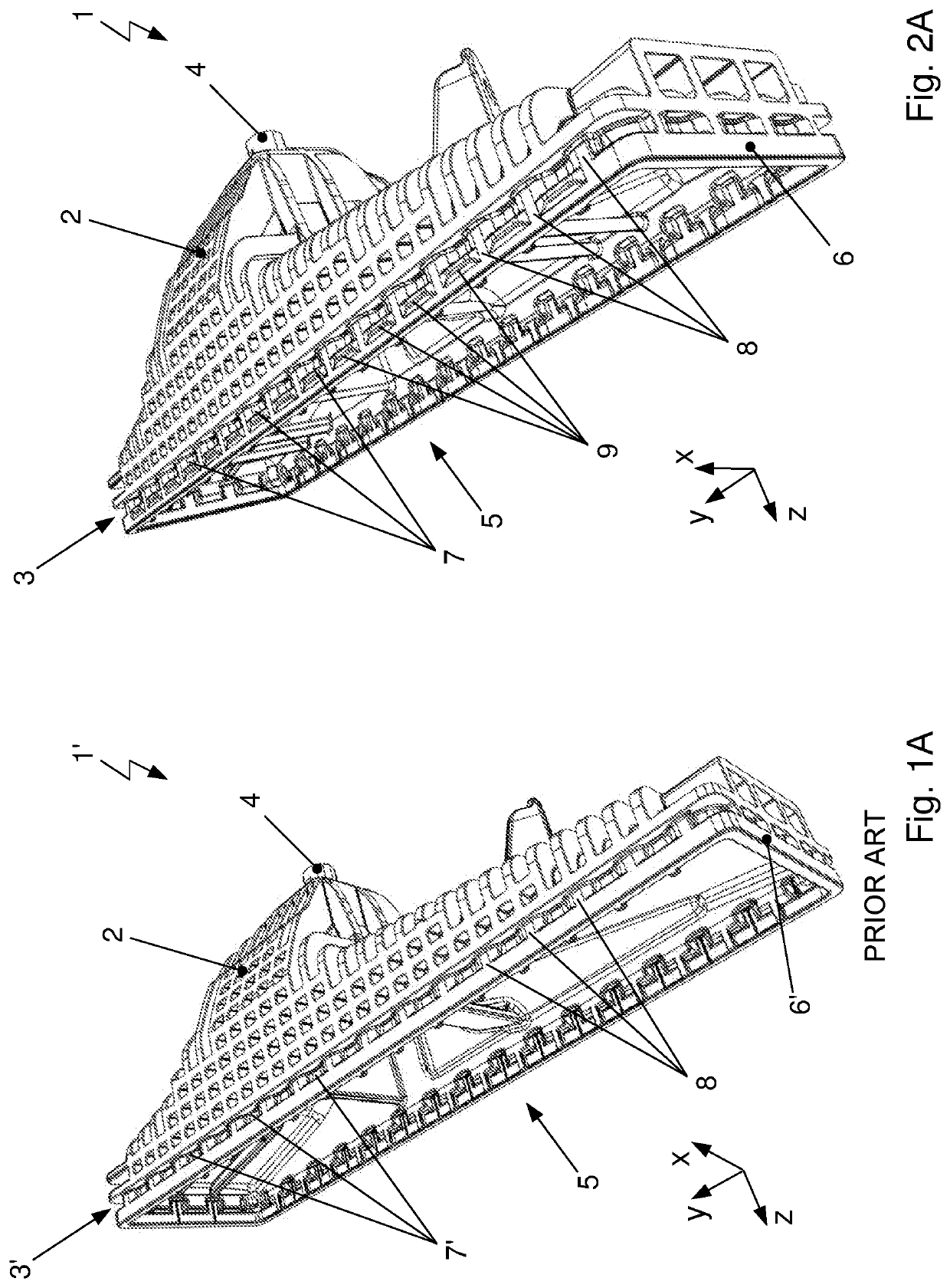
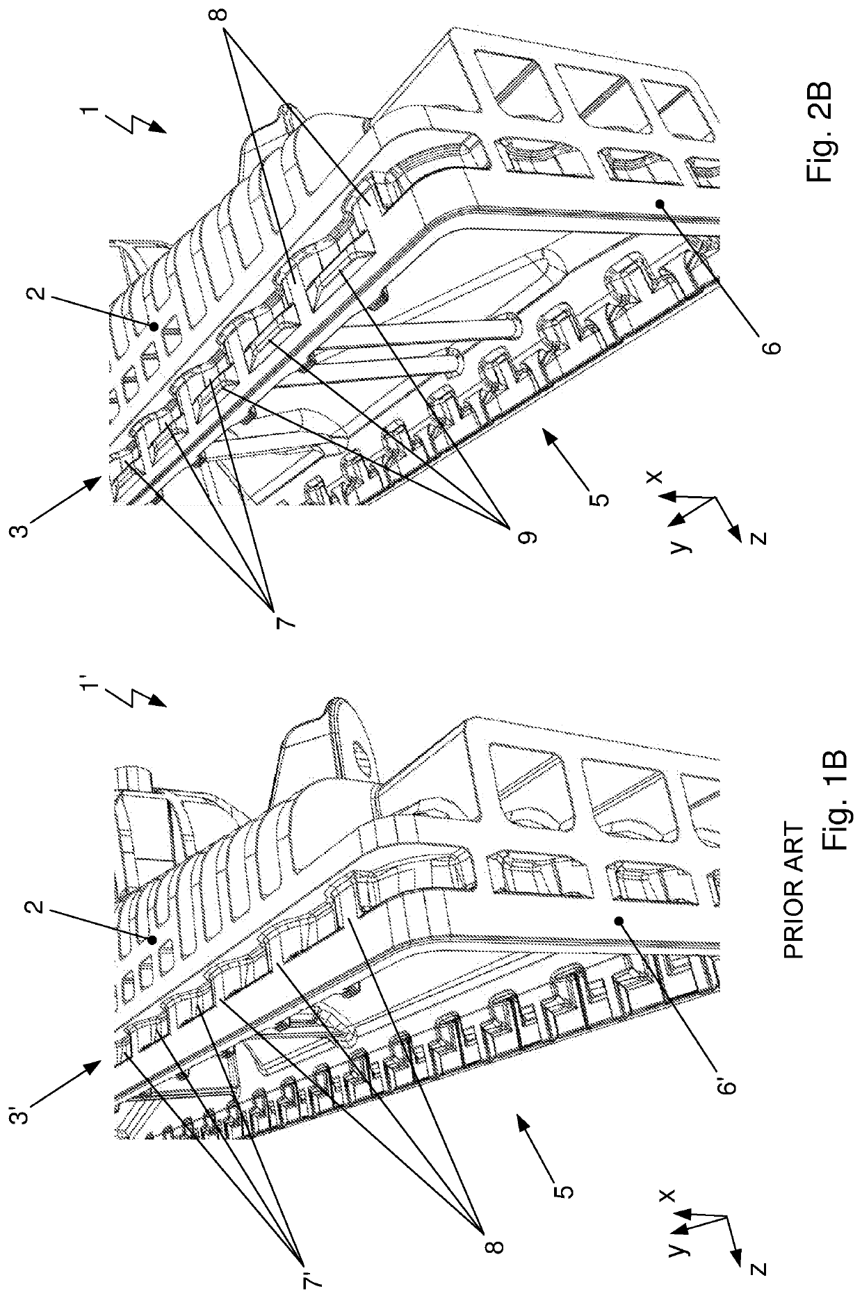
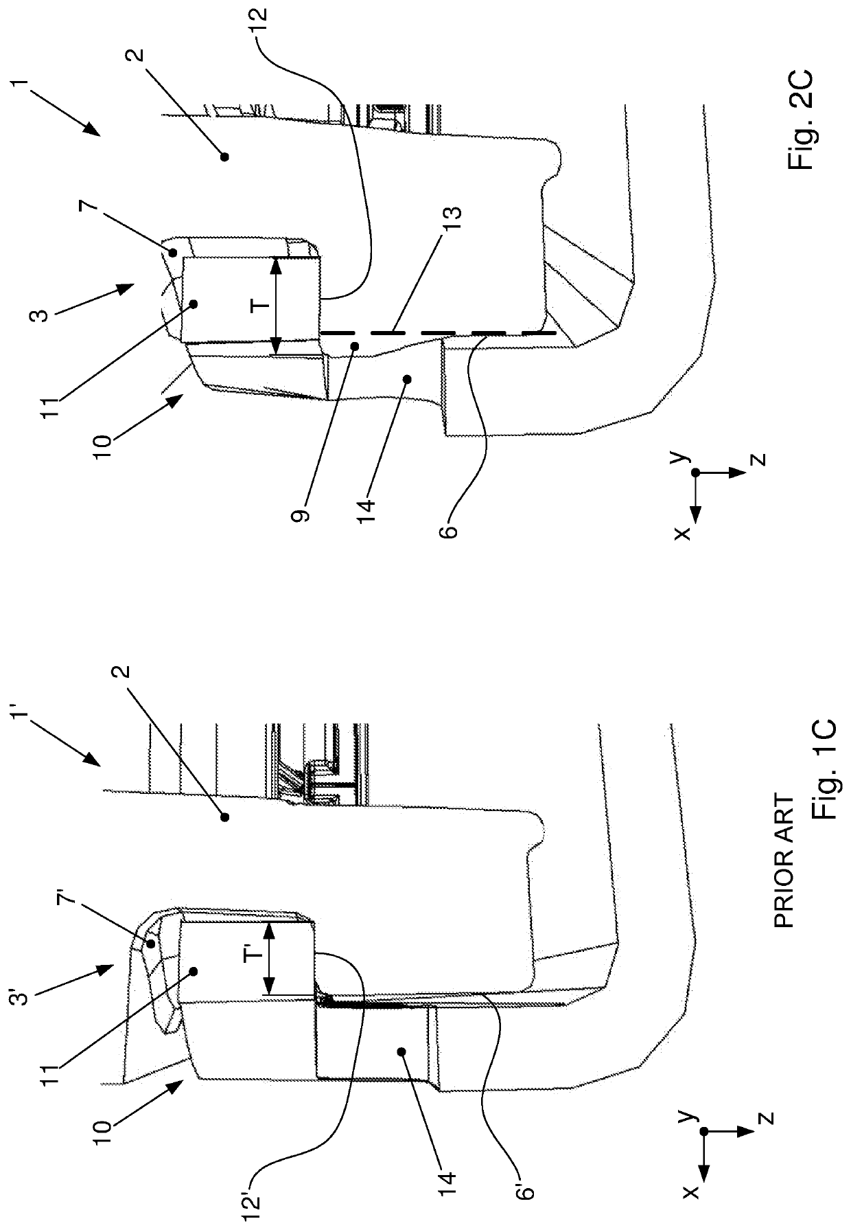
[0043]In FIGS. 1A and 1B is shown a first housing element 1′ of a device of prior art for heat transfer with a wall 2 and a connection region 3′ in perspective view. FIG. 1B depicts a section of the first housing element 1′ at an enlarged scale.

[0044]The first housing element 1′ is developed to enclose, together with a second, not shown, housing element, a volume. Within the volume a heat transfer arrangement, not shown, can be integrated through which flows a first fluid and around which flows a second fluid. Heat can hereby be exchanged between the fluids. One of the fluids flows herein through a passage inlet 4 developed in the wall 2 into the volume enclosed by the first housing element 1′ and by the second housing element, is routed specifically by the particular wall 2 of the housing element 1′ around the heat transfer arrangement and subsequently flows through a passage, not shown, out of the volume again.

[0045]The first housing element 1′ comprises a connection region 3′ in ...


PUM

PropertyMeasurementUnit
volumeaaaaaaaaaa
areaaaaaaaaaaa
depthaaaaaaaaaa

Abstract

A system for connecting housing elements of a device for heat transfer having a housing with a first housing element and a second housing element which are connectable with one another with face sides oriented toward one another and via a connection under form closure. Housing elements are herein in contact on another with side margins developed in proximity of front faces. The first latching elements are implemented as recesses each with a flat surface oriented in parallel to front face. On an outer side of side margin of first housing element between each first latching element and front face, a shaping is developed protruding from side margin, which comprises on a side facing first latching element a flat surface disposed in the plane spanned by flat surface of first latching element. Flat surfaces of first latching element and the shaping form a contiguous bearing area for second latching element.

Description

[0001]This application claims priority from German Patent Application No. 102018109233.4 filed on Apr. 18, 2018, which is hereby incorporated herein by reference in its entirety.FIELD OF THE INVENTION[0002]The invention relates to a system for connecting housing elements of a device for heat transfer, in particular for application in a motor vehicle. The device comprises a housing with a first housing element and a second housing element which are connectable with one another with their front faces oriented toward one another and across a connection under form closure.BACKGROUND OF THE INVENTION[0003]Heat transfer devices of the above described class serve primarily for cooling exhaust gas, particularly of internal combustion engines, which is mixed with the fresh air to be supplied to the combustion process in order to reach, on the one hand, a reduction of the oxygen content. On the other hand, the heat energy of the exhaust gas is also utilized. The heat transfer device is utiliz...

Claims


Application Information

Patent Timeline
Patent Type & Authority Patents(United States)
IPC IPC(8): F02M26/00F02M26/29F02B29/04F02M26/12
CPCF02M26/29F02B29/045F02M26/12F01N3/0205F28F9/001F28F9/0226F28F21/06F28F21/084F28F2009/0292F28F2225/08F28F2275/085F28D2021/0082F28F2275/14
Inventor HRUZA, HYNEKGREGUS-KOLLAR, JANKRAJCA, KAREL
Owner HANON SYST
Learn More