Variable displacement vane pump having multiple dampening springs

a vane pump and variable displacement technology, applied in the direction of machines/engines, liquid fuel engines, positive displacement liquid engines, etc., can solve the problems of not being able to sufficiently improve the fuel consumption and engine output, and achieve the effect of increasing or decreasing the volume of the hydraulic chamber, and reducing the eccentric amount of the cam ring

Inactive Publication Date: 2015-04-14
HITACHI AUTOMOTIVE SYST LTD
View PDF9 Cites 3 Cited by
  • Summary
  • Abstract
  • Description
  • Claims
  • Application Information

AI Technical Summary

Benefits of technology

[0004]However, in this variable displacement pump, the eccentric amount of the cam ring is decreased so as to improve the fuel consumption and so on by decreasing the driving torque of the pump. Accordingly, after each of the actuations of the cam ring, that is, in a time period immediately before the second predetermined hydraulic pressure is needed after the discharge pressure reaches the first predetermined hydraulic pressure, and in a time period after the discharge pressure reaches the second predetermined hydraulic pressure, it is desirable that the increase of the discharge pressure according to the increase of the engine speed is not generated.

Problems solved by technology

However, in the conventional variable displacement pump, the springs are used for restricting the actuation of the cam ring.
Therefore, it is not possible to sufficiently improve the fuel consumption and the output of the engine.

Method used


Image

  • Variable displacement vane pump having multiple dampening springs
  • Variable displacement vane pump having multiple dampening springs
  • Variable displacement vane pump having multiple dampening springs

Examples


first embodiment

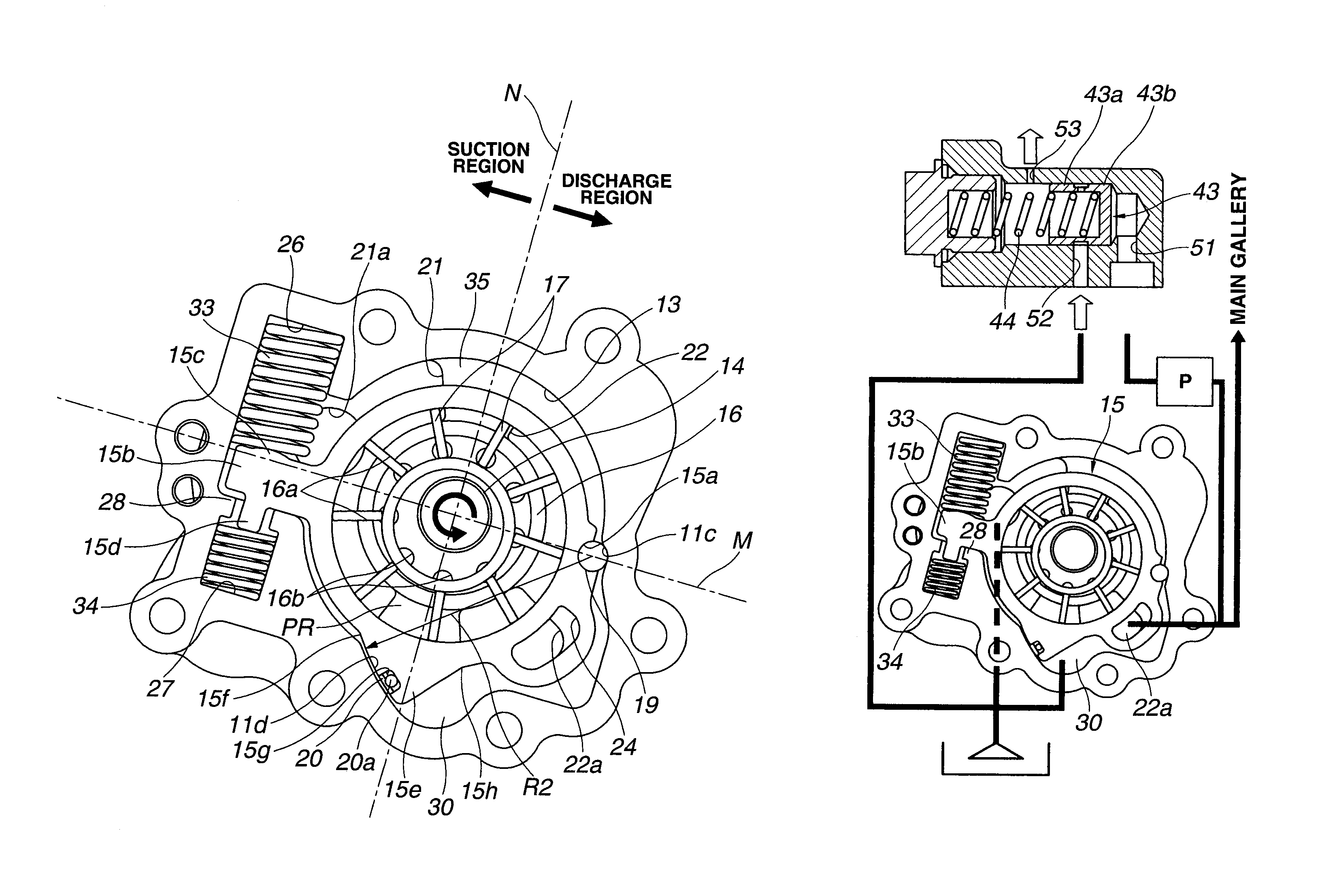
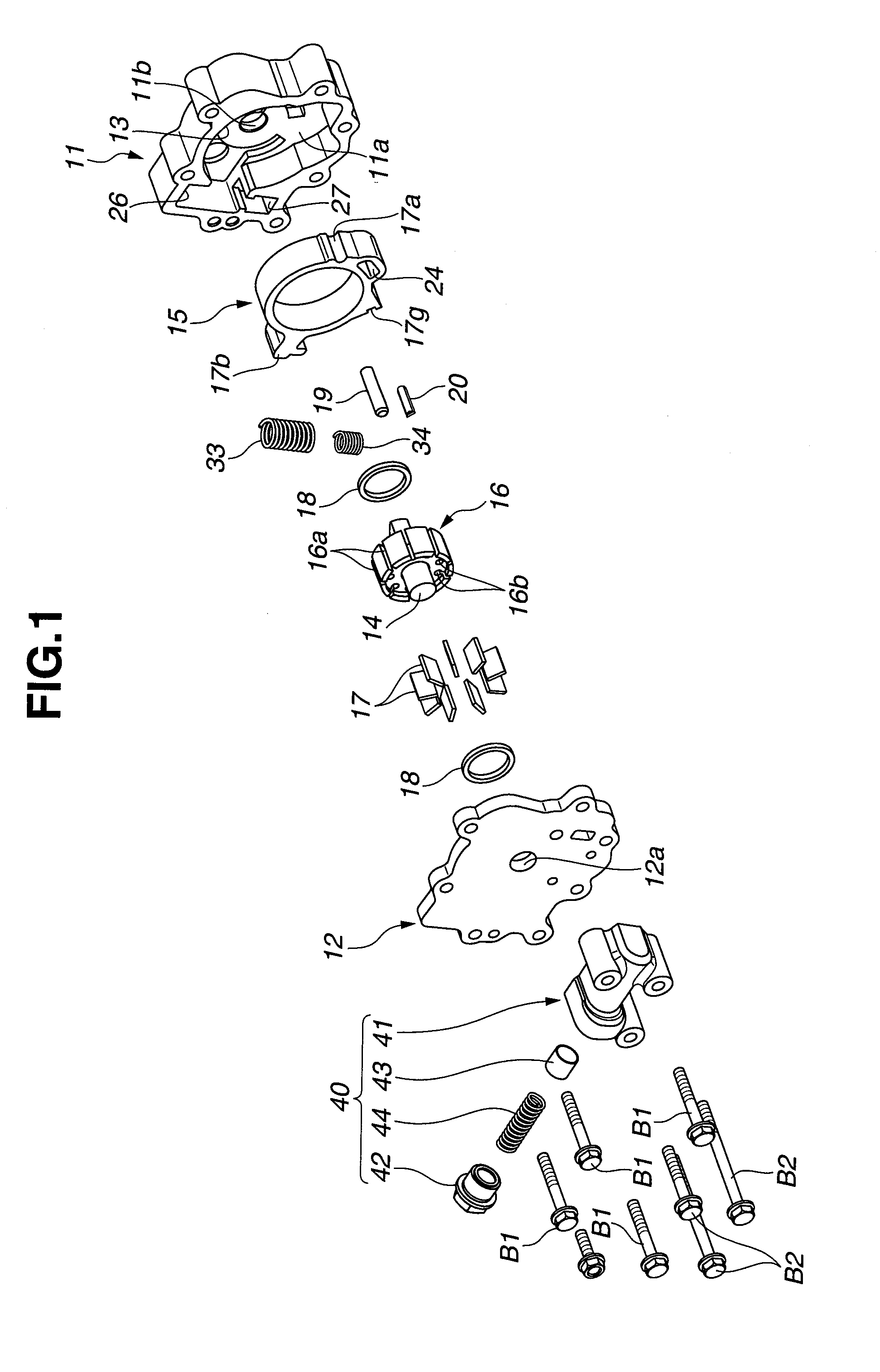
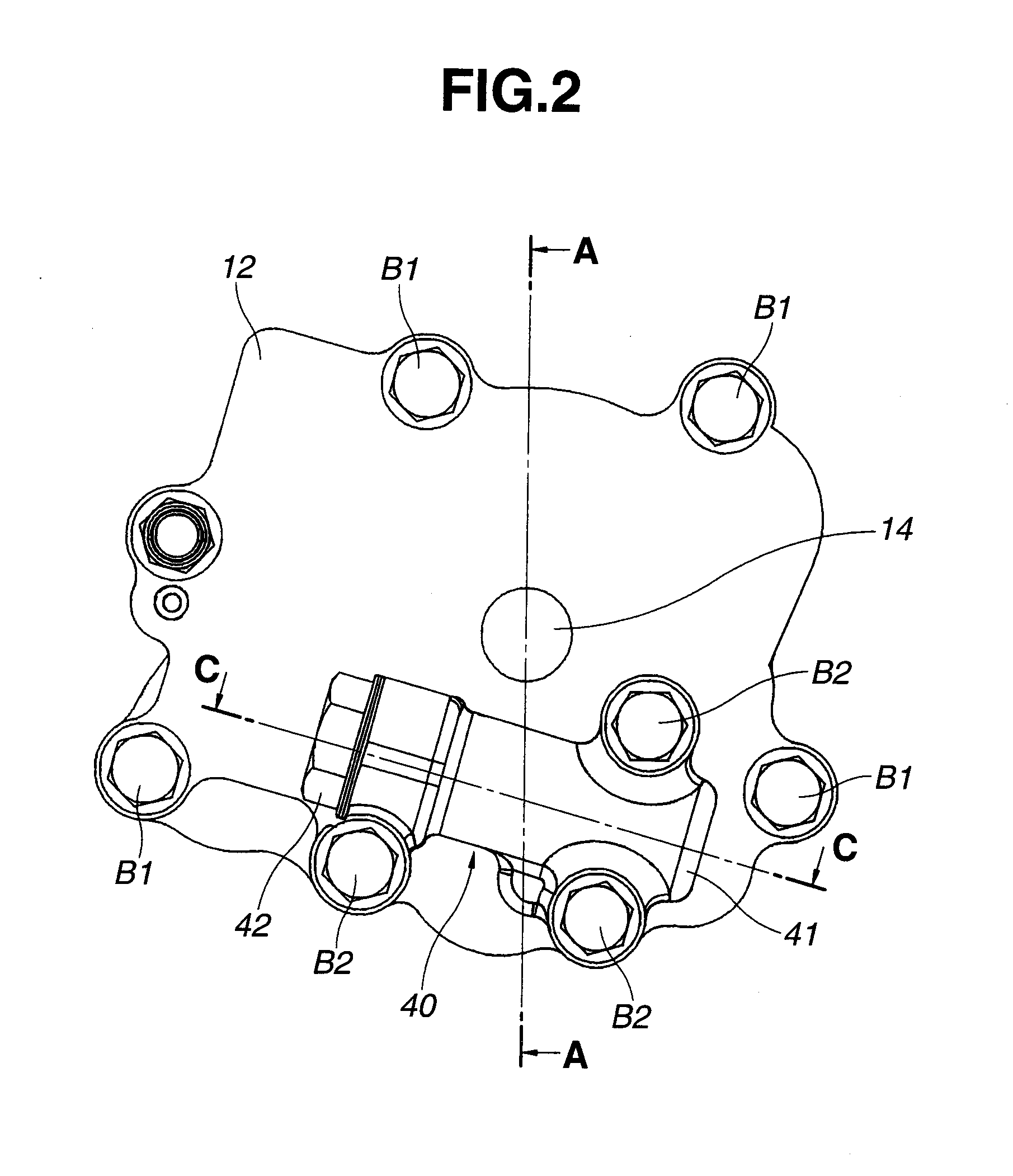
[0023]FIGS. 1-9 show an oil pump according to the present invention. As shown in FIGS. 1-4, this oil pump 10 includes a pump housing which is provided at a front end portion of a cylinder block of the internal combustion engine (not shown) and a front end portion of a balancer apparatus, and which includes a pump body 11 which has a substantially U-shaped longitudinal section, and which includes a pump receiving chamber 13 that has an opening located on one end side of pump body 11, and a cover member 12 closing the opening of the pump body 11; a driving shaft 14 which penetrates through a substantially center portion of pump receiving chamber 13, and which is rotatably driven by a crank shaft (not shown), a balancer shaft (not shown) and so on; a cam ring 15 which is a movable member movably (swingably) disposed within pump receiving chamber 13; a pump constituting (forming) section which is disposed radially inside cam ring 15, and which is arranged to increase or decrease volumes...

second embodiment

[0066]That is, in the oil pump valve element 43 is formed into the substantially solid cylindrical shape. Valve element 43 includes first and second land portions 43a and 43b which are located on both sides of valve element 43, and which have larger diameter. Moreover, valve element 43 includes an annular space 54 which has a relatively larger width, which is located at a substantially central portion of valve element 43, which has a stepped shape to decrease its diameter, and which is separated by first and second land portions 43a and 43b and the inner circumference surface of valve body 41. By this structure, when valve element 43 is pressed against stepped portion 41c of valve body 41, first port 51 is closed by second land portion 43b, and second port 52 and third port 53 are connected with each other through annular space 54 (cf. FIG. 11A). On the other hand, when valve element 43 is moved toward the first end of valve body 41, third port 53 is closed by second land portion 4...

third embodiment

[0071]In this way, the switching control by control valve 40 is electrically performed by using solenoid valve SV. Accordingly, the oil pump is not influenced by the abrasions of various portions of pump 10, and the variation of the hydraulic pressure that is caused by varying kind of the hydraulic fluid. Consequently, it is possible to smoothly and rapidly actuate (move) cam ring 15 in the section b in FIG. 8. Consequently, it is possible to more effectively suppress the power loss in this section b. Therefore, it is possible to further improve the fuel consumption.

[0072]Moreover, in this embodiment, port switching hydraulic pressure Pk is determined in consideration of the engine speed, the water temperature, the oil temperature, and so on of the internal combustion engine. Accordingly, it is possible to more appropriately control control valve 40.

[0073]In this oil pump according to the third embodiment, a linear solenoid valve can be employed as the solenoid valve SV. With this,...


PUM


Abstract

A variable displacement pump includes: a first urging member arranged to urge the cam ring in a direction to increase the eccentric amount; a second urging member arranged to urge the cam ring in a direction to decrease the eccentric amount; a control hydraulic chamber arranged to receive a discharge pressure, and thereby to move the cam ring against the urging force of the first urging member; and a hydraulic pressure introduction section configured to introduce the discharge pressure to the control hydraulic chamber when the discharge pressure becomes greater than a predetermined pressure which is in a range where the cam ring is movable against a resultant force of the urging forces of the first and second urging members, and where the cam ring is not movable only against the urging force of the first urging member.

Description

BACKGROUND OF THE INVENTION[0001]This invention relates to a variable displacement pump arranged to supply a hydraulic fluid to sliding portions and so on of an internal combustion engine for a vehicle.[0002]U.S. Patent Application Publication No. 2009 / 0285707 A1 (corresponding to Internal Publication Number WO 2008 / 003169 A1) discloses a vane type variable displacement oil pump. This variable displacement oil pump includes a first spring arranged to urge a cam ring in a direction (hereinafter, referred to as an eccentric direction) to increase an eccentric amount of the cam ring with respect to a center of a rotation of a rotor, a second spring arranged to urge the cam ring in the eccentric direction when the eccentric amount of the cam ring becomes equal to or smaller than a predetermined amount, and a control hydraulic chamber separated between a pump housing and the cam ring. This variable displacement pump is arranged to control the eccentric amount of the cam ring by urging fo...

Claims


Application Information

Patent Timeline
Patent Type & Authority Patents(United States)
IPC IPC(8): F04B17/00F04B1/06F04B49/00F01C20/18F04C2/344F04C14/22F04C14/24
CPCF04C2/3442F04C14/223F04C14/226F04C14/24F04C2270/58F04C2270/80
Inventor OHNISHI, HIDEAKISAGA, KOJIWATANABE, YASUSHI
Owner HITACHI AUTOMOTIVE SYST LTD
Why Eureka
Try Eureka