Variable Displacement Pump
a variable-discharge pump and pump body technology, applied in the direction of liquid fuel engines, machines/engines, rotary piston liquid engines, etc., can solve the problems of not being able to sufficiently improve the fuel consumption and engine output, and achieve the effects of increasing or decreasing the volume of the hydraulic chamber, and reducing the eccentric amount of the cam ring
- Summary
- Abstract
- Description
- Claims
- Application Information
AI Technical Summary
Benefits of technology
Problems solved by technology
Method used
Image
Examples
first embodiment
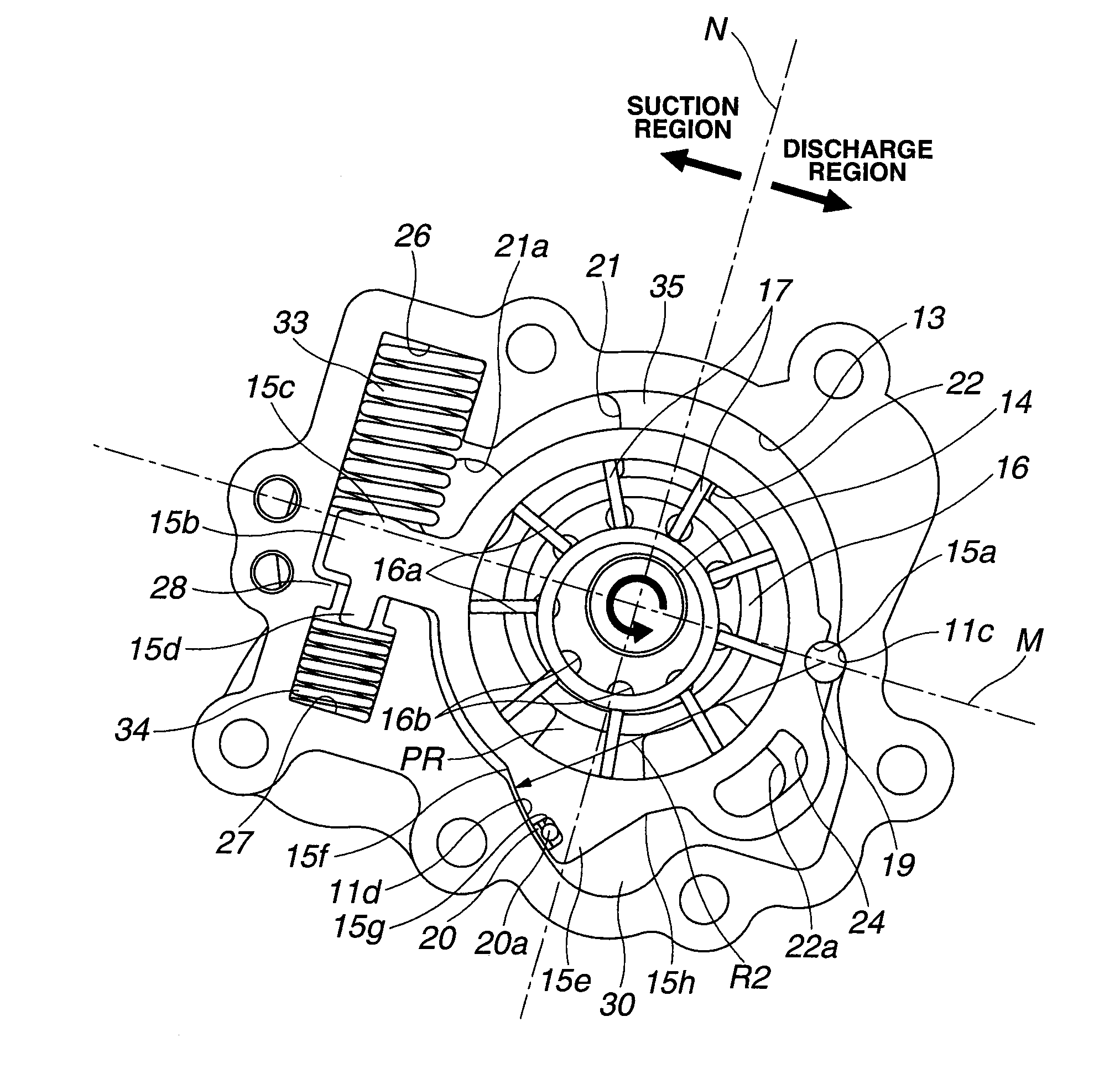
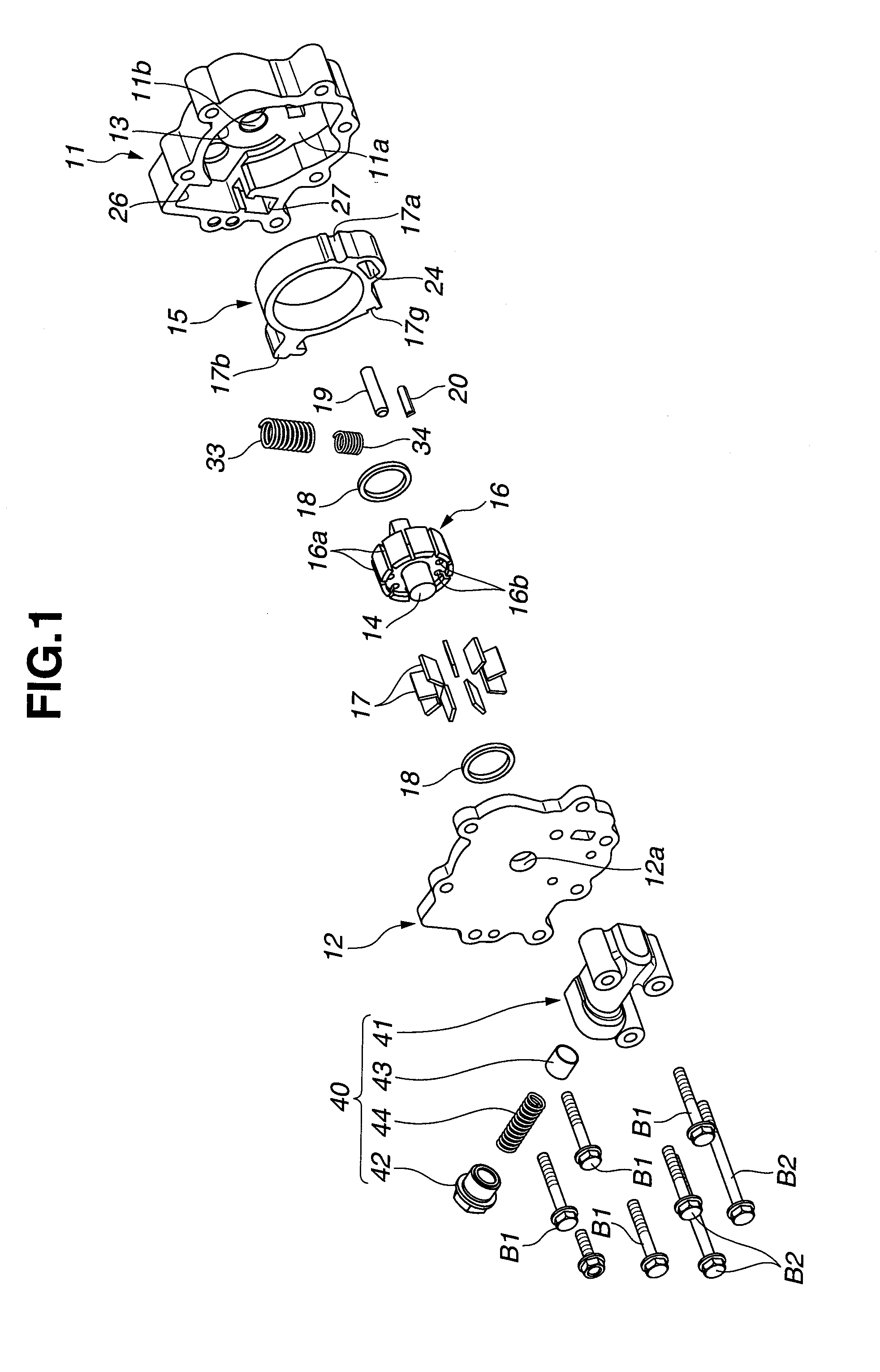
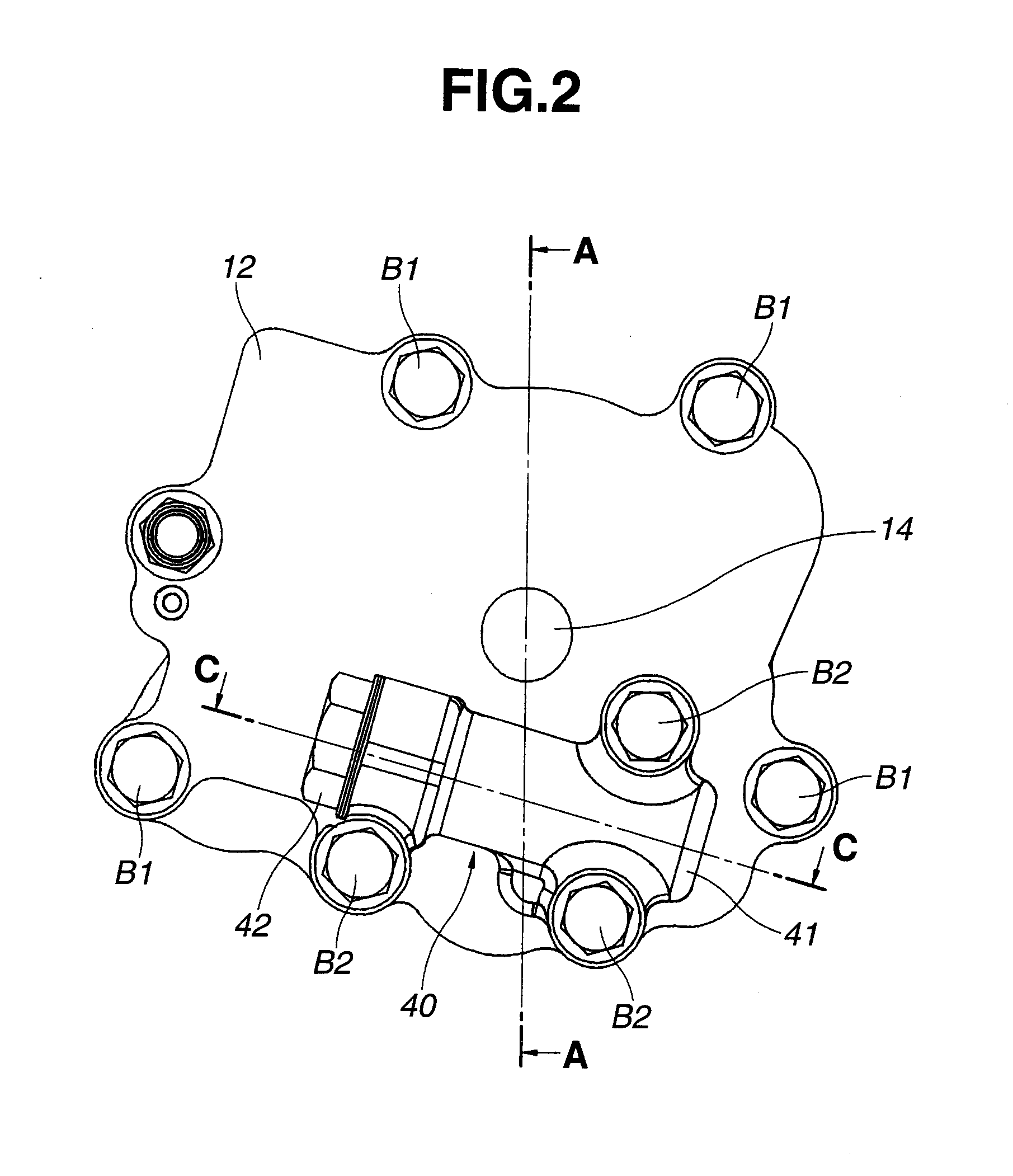
[0023]FIGS. 1-9 show an oil pump according to the present invention. As shown in FIGS. 1-4, this oil pump 10 includes a pump housing which is provided at a front end portion of a cylinder block of the internal combustion engine (not shown) and a front end portion of a balancer apparatus, and which includes a pump body 11 which has a substantially U-shaped longitudinal section, and which includes a pump receiving chamber 13 that has an opening located on one end side of pump body 11, and a cover member 12 closing the opening of the pump body 11; a driving shaft 14 which penetrates through a substantially center portion of pump receiving chamber 13, and which is rotatably driven by a crank shaft (not shown), a balancer shaft (not shown) and so on; a cam ring 15 which is a movable member movably (swingably) disposed within pump receiving chamber 13; a pump constituting (forming) section which is disposed radially inside cam ring 15, and which is arranged to increase or decrease volumes...
second embodiment
[0066]That is, in the oil pump valve element 43 is formed into the substantially solid cylindrical shape. Valve element 43 includes first and second land portions 43a and 43b which are located on both sides of valve element 43, and which have larger diameter. Moreover, valve element 43 includes an annular space 54 which has a relatively larger width, which is located at a substantially central portion of valve element 43, which has a stepped shape to decrease its diameter, and which is separated by first and second land portions 43a and 43b and the inner circumference surface of valve body 41. By this structure, when valve element 43 is pressed against stepped portion 41c of valve body 41, first port 51 is closed by second land portion 43b, and second port 52 and third port 53 are connected with each other through annular space 54 (cf. FIG. 11A). On the other hand, when valve element 43 is moved toward the first end of valve body 41, third port 53 is closed by second land portion 4...
third embodiment
[0071]In this way, the switching control by control valve 40 is electrically performed by using solenoid valve SV. Accordingly, the oil pump is not influenced by the abrasions of various portions of pump 10, and the variation of the hydraulic pressure that is caused by varying kind of the hydraulic fluid. Consequently, it is possible to smoothly and rapidly actuate (move) cam ring 15 in the section b in FIG. 8. Consequently, it is possible to more effectively suppress the power loss in this section b. Therefore, it is possible to further improve the fuel consumption.
[0072]Moreover, in this embodiment, port switching hydraulic pressure Pk is determined in consideration of the engine speed, the water temperature, the oil temperature, and so on of the internal combustion engine. Accordingly, it is possible to more appropriately control control valve 40.
[0073]In this oil pump according to the third embodiment, a linear solenoid valve can be employed as the solenoid valve SV. With this,...
PUM
 Abstract
Description
Claims
Application Information
 - R&D
- Intellectual Property
- Life Sciences
- Materials
- Tech Scout
- Unparalleled Data Quality
- Higher Quality Content
- 60% Fewer Hallucinations
Browse by: Latest US Patents, China's latest patents, Technical Efficacy Thesaurus, Application Domain, Technology Topic, Popular Technical Reports.
© 2025 PatSnap. All rights reserved.Legal|Privacy policy|Modern Slavery Act Transparency Statement|Sitemap|About US| Contact US: help@patsnap.com


