Remote-control flying copter and method

a flying copter and remote control technology, applied in the field of helicopters, can solve the problems of limited design set for how these craft are constructed, damage, craft crash, etc., and achieve the effect of convenient us

Active Publication Date: 2015-04-14
QFO LABS
View PDF171 Cites 83 Cited by
  • Summary
  • Abstract
  • Description
  • Claims
  • Application Information

AI Technical Summary

Benefits of technology

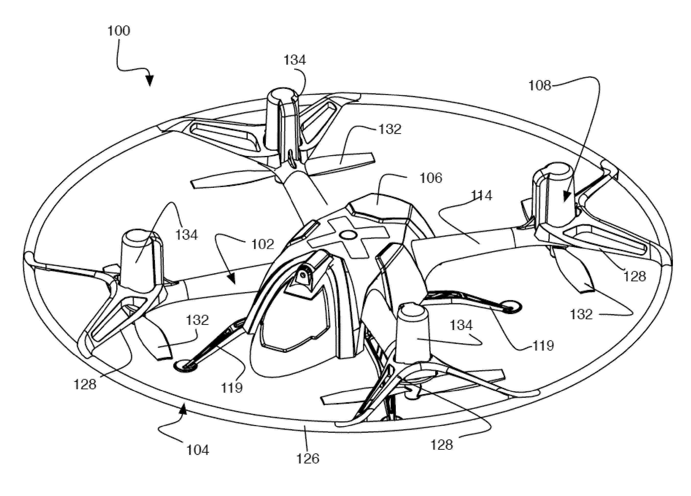
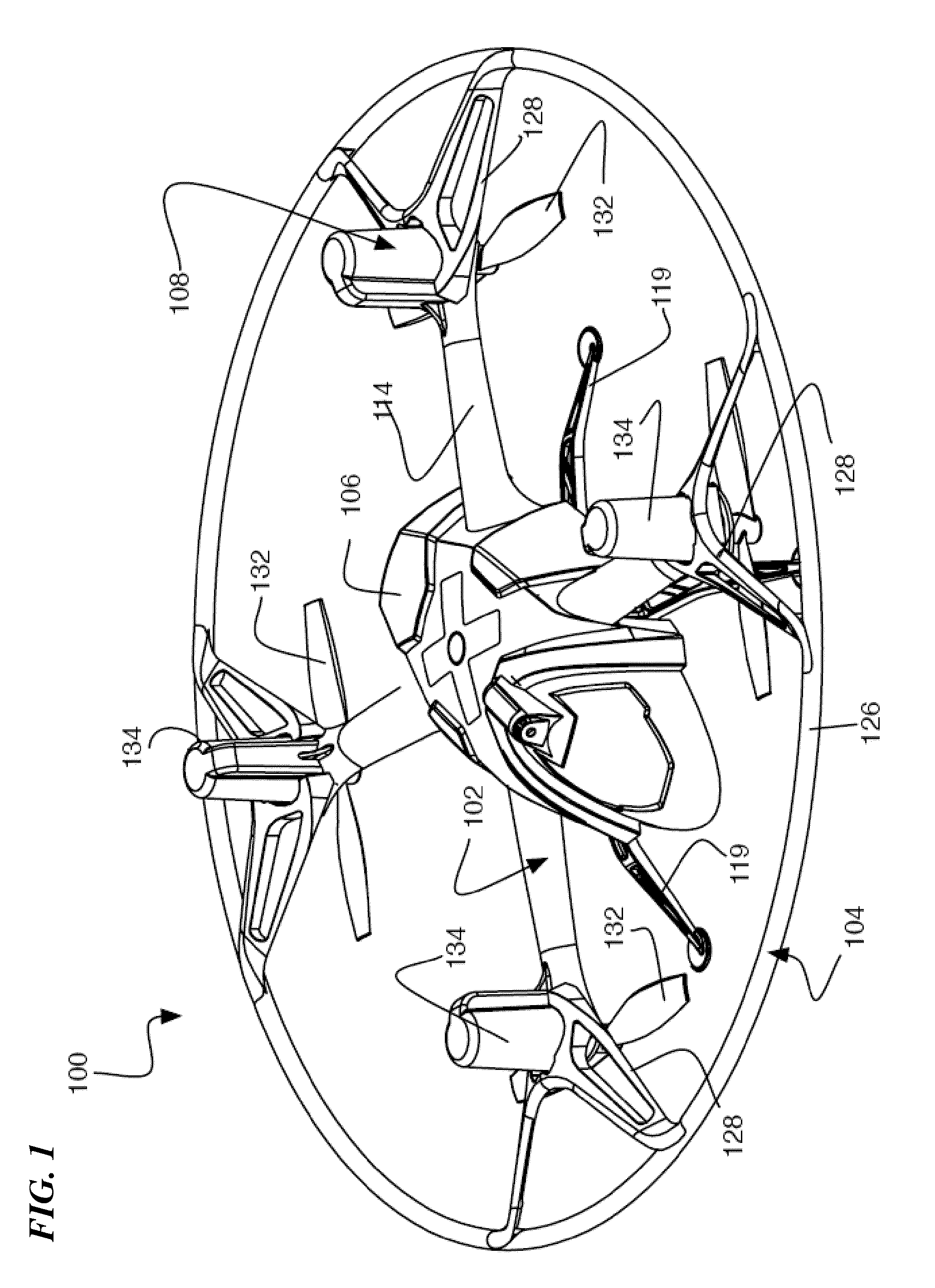
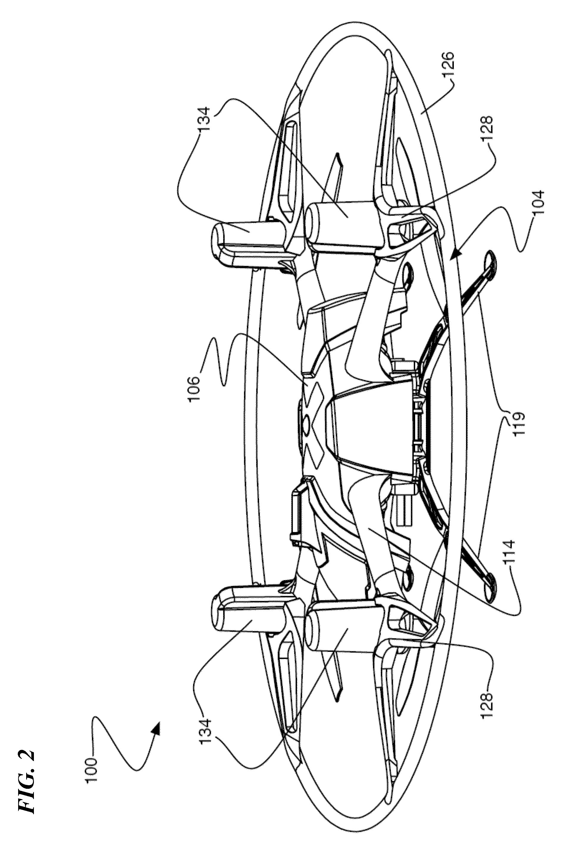
[0011]In various embodiments, a smaller, hovering remote-control flying craft includes features to support aerial game play based on both infrared (IR) and radio frequency (RF) communications, including a pairing button, an infrared emitter and sensor configured for aerial game play, a high-intensity light-emitting diode (LED) output for indicating team selection, and a vacuum-formed shell with windows and internal reflective surfaces for enhancing the visibility of light-emitting diode (LED) output.
[0013]Embodiments of the smaller, hovering remote-control flying craft of the present invention are small enough to safely fly in small indoor areas, but powerful enough to fly outdoors. Due to the rugged, lightweight design and only the four motors as moving parts, the hovering remote-control flying craft of the present invention is more durable than existing designs.
[0016]The single-handed remote controller can be tilted forward, back, left, or right, and the corresponding controlled flying vehicle responds accordingly, thereby providing total one-handed control over the vehicle. In embodiments, the controller has an ergonomic design made for the human hand. In embodiments, the same controller is comfortable and easy to use both for right-handed or left-handed pilots. Moreover, the controller exemplifies U.S. Air Force Human Factors data considerations for aircraft controls, creating a realistic and high-tech interface.

Problems solved by technology

A problem with current designs for these kinds of smaller, hovering remote-control flying craft is that the competing design considerations of weight, cost and performance have resulted in a very limited set of designs for how these craft are constructed.
Running the rotors into an obstacle, like a ceiling when flying indoors, almost always causes the craft to crash and potentially suffer damage as a result.
These existing designs for smaller, hovering remote-control flying craft suffer from various problems, including cost of manufacture, ease of operation, accuracy of navigation, durability, and safety during operation, among others problems.

Method used


Image

  • Remote-control flying copter and method
  • Remote-control flying copter and method
  • Remote-control flying copter and method

Examples


Embodiment Construction

[0041]Although the following detailed description contains many specifics for the purpose of illustration, a person of ordinary skill in the art will appreciate that many variations and alterations to the following details are within the scope of the invention. Very narrow and specific examples are used to illustrate particular embodiments; however, the invention described in the claims is not intended to be limited to only these examples, but rather includes the full scope of the attached claims. Accordingly, the following preferred embodiments of the invention are set forth without any loss of generality to, and without imposing limitations upon the claimed invention. Further, in the following detailed description of the preferred embodiments, reference is made to the accompanying drawings that form a part hereof, and in which are shown by way of illustration specific embodiments in which the invention may be practiced. It is understood that other embodiments may be utilized and s...


PUM


Abstract

A hovering remote-control flying craft having a molded frame assembly includes a plurality of arms extending from a center body with an electric motor and corresponding propeller on each arm. In various embodiments, the motor and propeller are mounted downward-facing at a distal portion of each arm with a motor cover over the motor. The center body can be formed of a two-piece molded structure that sandwiches a circuit board to provide structural support for the frame. The circuit board can include a plurality of tabs that facilitate mounting of wire connectors, and can also provide antennas and emitters for both IR and RF communications. In some embodiments, a removable safety ring protects the propellers from lateral contact.

Description

CROSS-REFERENCE TO RELATED APPLICATIONS[0001]This invention claims benefit of U.S. Provisional Patent Application 61 / 710,665 filed Oct. 5, 2012, titled “REMOTE-CONTROL FLYING COPTER,” and claims benefit of U.S. Provisional Patent Application 61 / 710,671 filed Oct. 5, 2012, titled “WIRELESS COMMUNICATION SYSTEM FOR GAME PLAY WITH MULTIPLE REMOTE CONTROL FLYING CRAFT,” each of which is incorporated herein by reference in its entirety.[0002]This invention is also related to prior U.S. Design patent application Ser. No. 29 / 433,939 filed Oct. 5, 2012, titled “Single-Handed Controller for a Remote Control Flying Craft” (which issued as U.S. Design Pat. No. D691,217 on Oct. 8, 2013); and to U.S. patent application Ser. No. 13 / 843,490, filed on even date herewith, titled “WIRELESS COMMUNICATION SYSTEM FOR GAME PLAY WITH MULTIPLE REMOTE-CONTROL FLYING CRAFT”; each of which is incorporated herein by reference in its entirety.TECHNICAL FIELD[0003]The invention relates generally to the field of ...

Claims


Application Information

Patent Timeline
Patent Type & Authority Patents(United States)
IPC IPC(8): A63H27/127A63F13/00A63H27/00A63H30/04
CPCA63H27/12A63F13/00A63H30/04B64C2203/00G05D1/0033B64U10/13B64U50/19B64U2201/20A63F13/235A63F13/245A63F13/837A63H17/00A63H17/32A63H27/00A63H33/26A63H2200/00F21L4/027F21V23/0435F41G1/36A63H13/00
Inventor CONDON, JOHN PAULFAIRMAN, JAMES EDWARDPEDERSEN, BRADLEY DEANKRAMER, THOMAS EDWARDMELANSON, SCOTT ANDREW
Owner QFO LABS
Why Eureka
Try Eureka