Water filter

a filter and water technology, applied in the field of water filters, can solve the problems of slow process, slow and cumbersome, and adverse health effects of contaminated water removal, and achieve the effect of reducing energy requirements and effective removal

Inactive Publication Date: 2015-04-14
CEDAR CREEK FILTERS LLLP
View PDF7 Cites 0 Cited by
  • Summary
  • Abstract
  • Description
  • Claims
  • Application Information

AI Technical Summary

Benefits of technology

[0005]The present invention is directed to an improved water filter that operates continuously with minimal energy requirements and is more effective in the removal of sludge and other pollutants from contaminated water sources.

Problems solved by technology

These concerns stem from the potential adverse health effects of the contaminated water reentering the aquifer.
Contaminated water removal has conventionally been a slow process, as the contaminants must be removed before transport.
This method is slow and cumbersome and requires many changes of the filter, causing serious time delays when filling the transport trucks.
However, as mentioned previously, frequent filter changes are required, substantially slowing the transport process.
Further, following scheduled filter replacements is crucial to eliminate the possibility of contamination, but not knowing the volume of sludge in the water does not allow for regular filter replacements.
This slows the filtering process, substantially increasing the waiting time and operating costs.
One of the key difficulties faced in using the sock method is the complexity of the contaminated water.
Filter life is dependent on how much of these components are present in the contaminated water and there is no easy way to segregate out the most damaging components to improve filter life.

Method used


Image

  • Water filter
  • Water filter
  • Water filter

Examples


Embodiment Construction

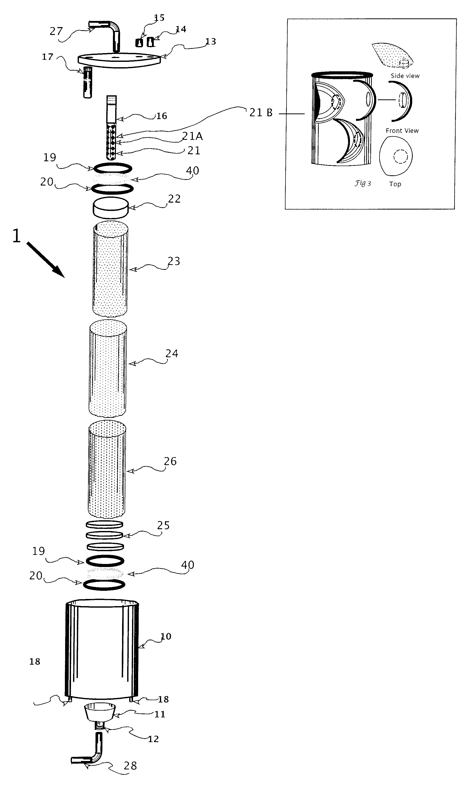
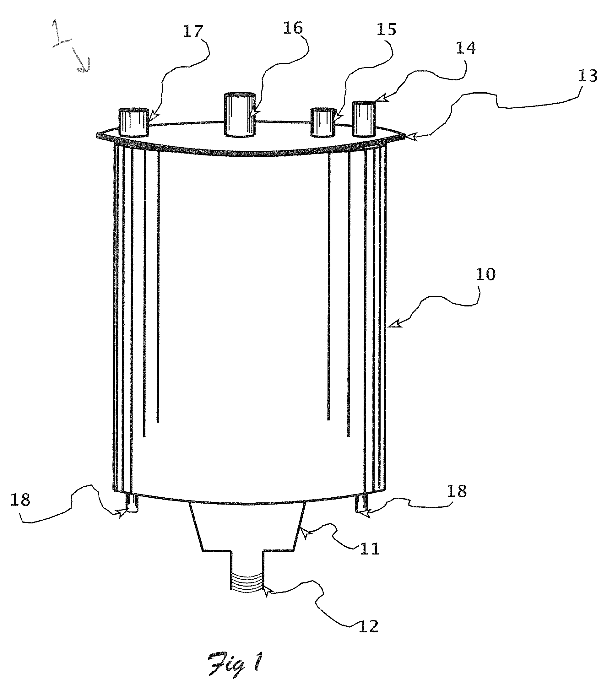
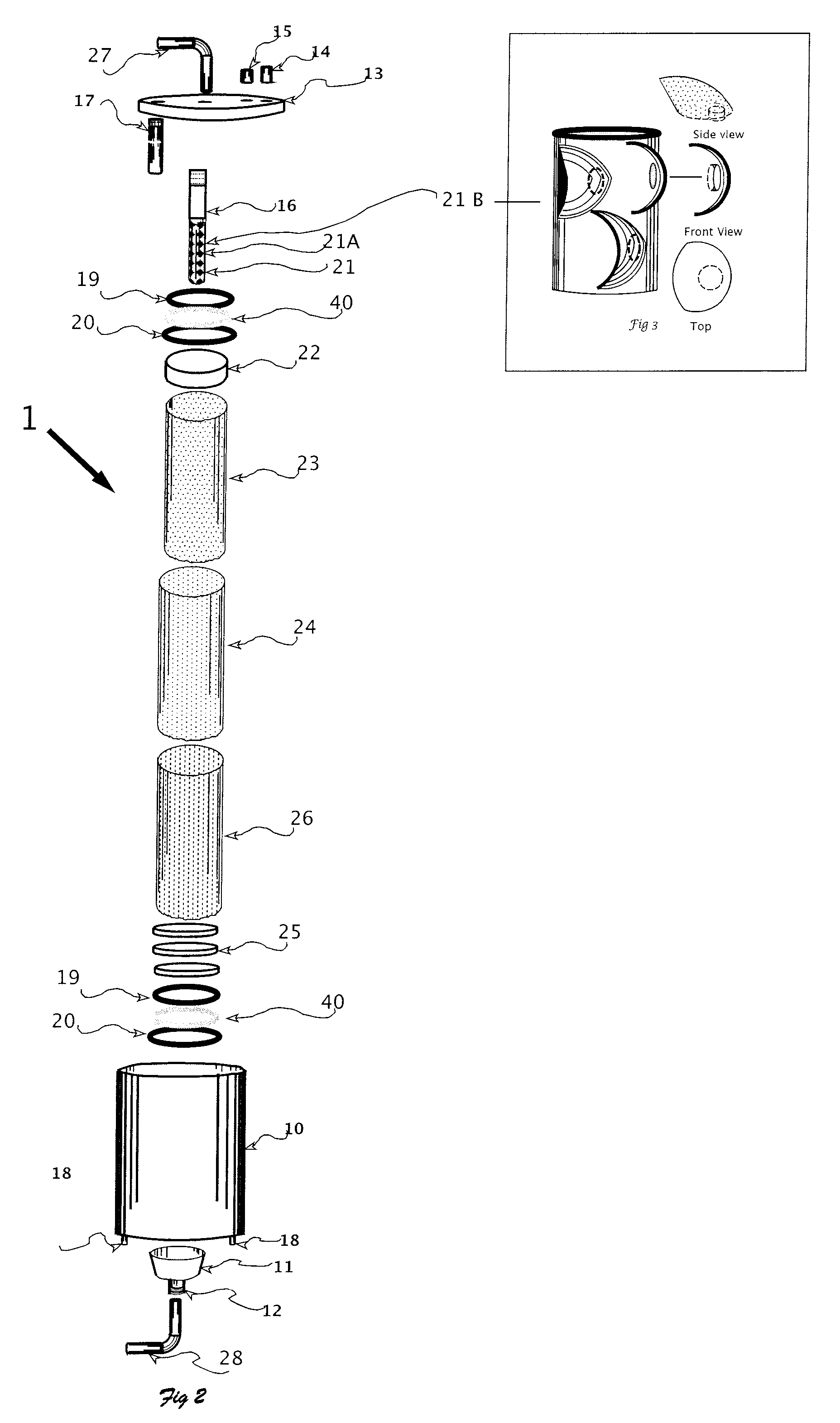
[0031]FIGS. 1 and 2 illustrate a water filter, generally designated by reference numeral 1, according to an exemplary embodiment of the present invention. Water filter 1 includes a housing 10, large piece debris basket 11, fitting 12, small, heavy particle outflow pipes 18 extending from the bottom of the housing 10, and a lid 13 with a retaining collar and seal that encloses the top of the housing 10. The size of the housing 10 may be selected according to the required capacity of the filter 1. An oil outflow pipe 14, a small, light particle outflow pipe 15, a main contaminated water inflow pipe 16 and discharge pipe 17 may pass through the lid 13. All of the pipes may have valves that control their rate of flow and which can be adjusted in order to control the operation of the filter 1. Discharge pipe 17 extends downwards into the perimeter of the housing 10 to draw filtered water out from below the floating oil and debris.

[0032]As described in more detail below, filter components...


PUM

PropertyMeasurementUnit
pressureaaaaaaaaaa
pressureaaaaaaaaaa
water pressureaaaaaaaaaa

Abstract

A water filter including a housing, at least one cylindrical filter component disposed within the housing, an inflow pipe extending through, and parallel to a longitudinal axis of, the at least one cylindrical filter component, the inflow pipe including a series of openings arranged along the length of the inflow pipe so as to cause a cyclonic motion of the contaminated water out of the inflow pipe and into contact with the at least one cylindrical filter component, a first outflow pipe that delivers filtered water from the at least one cylindrical filter component, and a second outflow pipe that delivers contaminants from the at least one cylindrical filter component.

Description

TECHNICAL FIELD[0001]The present invention is directed to the filtering of contaminated water generated during industrial processes such as oil drilling.BACKGROUND[0002]During an oil drilling process, debris (comprised of water, oil, stone, soil, metal fragments, mud and other components) is generated and stored in a pond adjacent to the drilling rig as sludge. This sludge must be treated according to industry standards set for maximum contaminant levels. These concerns stem from the potential adverse health effects of the contaminated water reentering the aquifer. The contaminated water, which is removed, must be trucked to disposal areas and pumped below the aquifer into detention areas, which are then sealed. Contaminated water removal has conventionally been a slow process, as the contaminants must be removed before transport. The only method currently available for removing contaminants from the water uses a sock type filter. This method is slow and cumbersome and requires many...

Claims


Application Information

Patent Timeline
Patent Type & Authority Patents(United States)
IPC IPC(8): B01D21/00B01D29/90B01D21/26B01D35/14B01D21/24B01D35/30
CPCB01D21/26B01D35/14B01D35/30B01D29/908B01D21/0012B01D21/0087B01D21/2405B01D21/267B01D2201/309
Inventor OLSON, SCOTTANDERSON, ROBERT A.
Owner CEDAR CREEK FILTERS LLLP
Why Eureka
Try Eureka