Snake tool adaptor

a technology of adaptors and snakes, applied in the field of adapters for snake cables, can solve the problems of inconvenient cleaning, inconvenient cleaning, and inconvenient cleaning of drains, and achieve the effect of convenient cleaning and convenient attachment of adaptors

Active Publication Date: 2015-04-28
KHONSARY CYRUS
View PDF15 Cites 9 Cited by
  • Summary
  • Abstract
  • Description
  • Claims
  • Application Information

AI Technical Summary

Benefits of technology

[0006]The subject invention meets the above-described need in the art by providing a snake tool adaptor capable of coupling commercially available heavy duty drain cleaning cables and attachments normally associated with heavy electric drain cleaners with a portable rotary driving tool such as a hand-held drill. More specifically, the snake tool adaptor of the subject invention is includes a shaft, typically polygonal in cross section for operable attachment to a the chuck of a power drill, coupling means for removable mating engagement with various

Problems solved by technology

They are not well suited on larger drain and sewer pipes which can have diameters of 3″ to 8″ (75 mm to 200 mm).
For instance, electric drain cleaners are relatively expensive, considerably heavy and are attendant with several safety risks.
It is not unusual for the electric drain cleaning machine alone (without accessories and attachments) to weigh in excess

Method used


Image

  • Snake tool adaptor
  • Snake tool adaptor
  • Snake tool adaptor

Examples


first embodiment

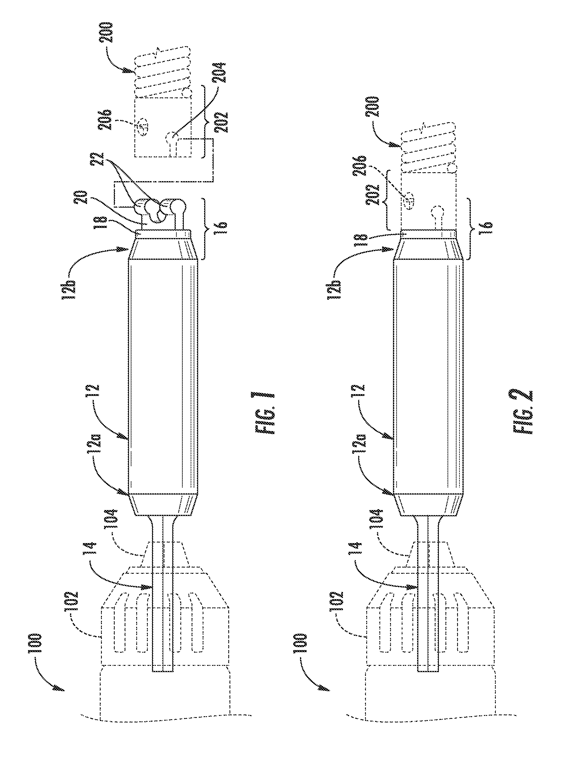
[0025]With continued reference to FIGS. 1 and 2, a coupling means is depicted, namely coupler 16. Coupler 16 is adapted for mating engagement with a heavy duty cable 200 having a RIDGID® brand female quick-connect coupling 202, manufactured by Ridge Tool Company, attached to its proximal end. Female coupling 202 includes a generally i-shaped (in cross-section) channel 204 disposed transversely through its distal end for slidably receiving a similarly shaped male member of coupler 16. Coupler 16 includes a disc-shaped base 18 having a first side fixedly attached to, or integrally formed with, the second end 12b of grip 12. The male member of coupler 16 is comprised of a c-shaped transverse member 20 projecting normal to the opposite side of base 18, the transverse member 20 terminating at each end of its c-shape in concentrically aligned cylinders 22. As will be appreciated by those skilled in the art, transverse member 20 and cylinders 22 are slidably received in channel 204 of fema...

second embodiment

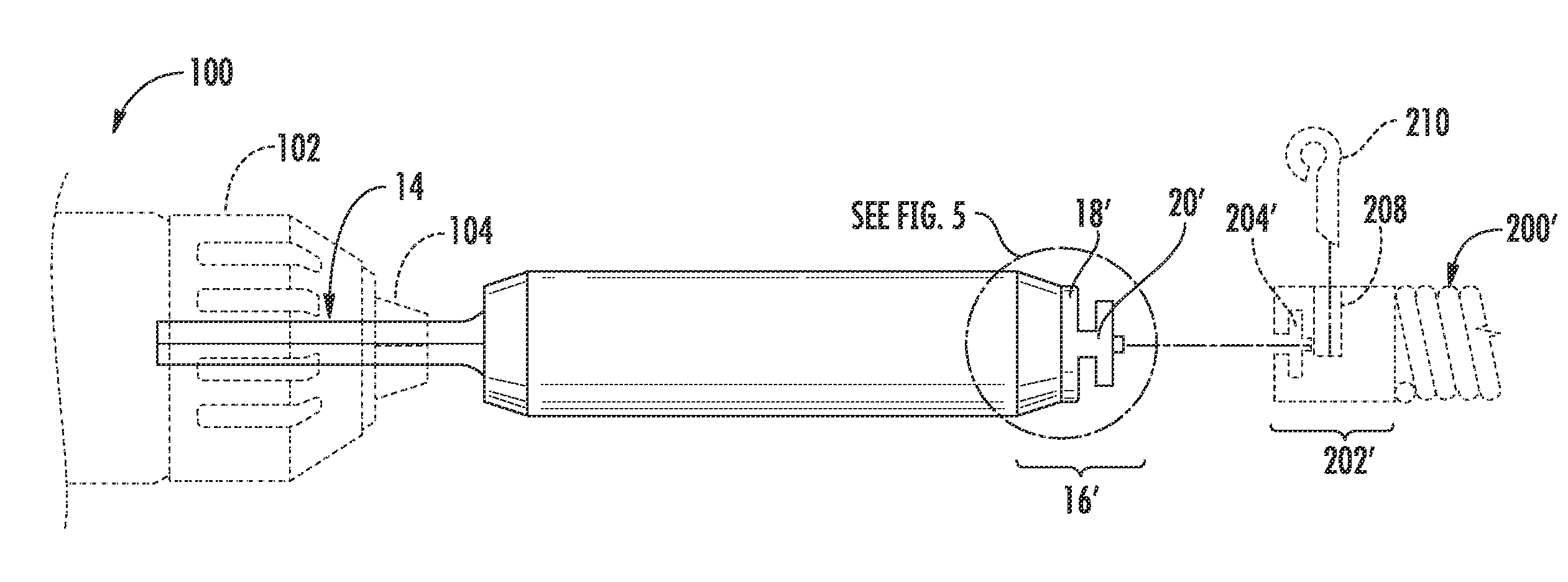
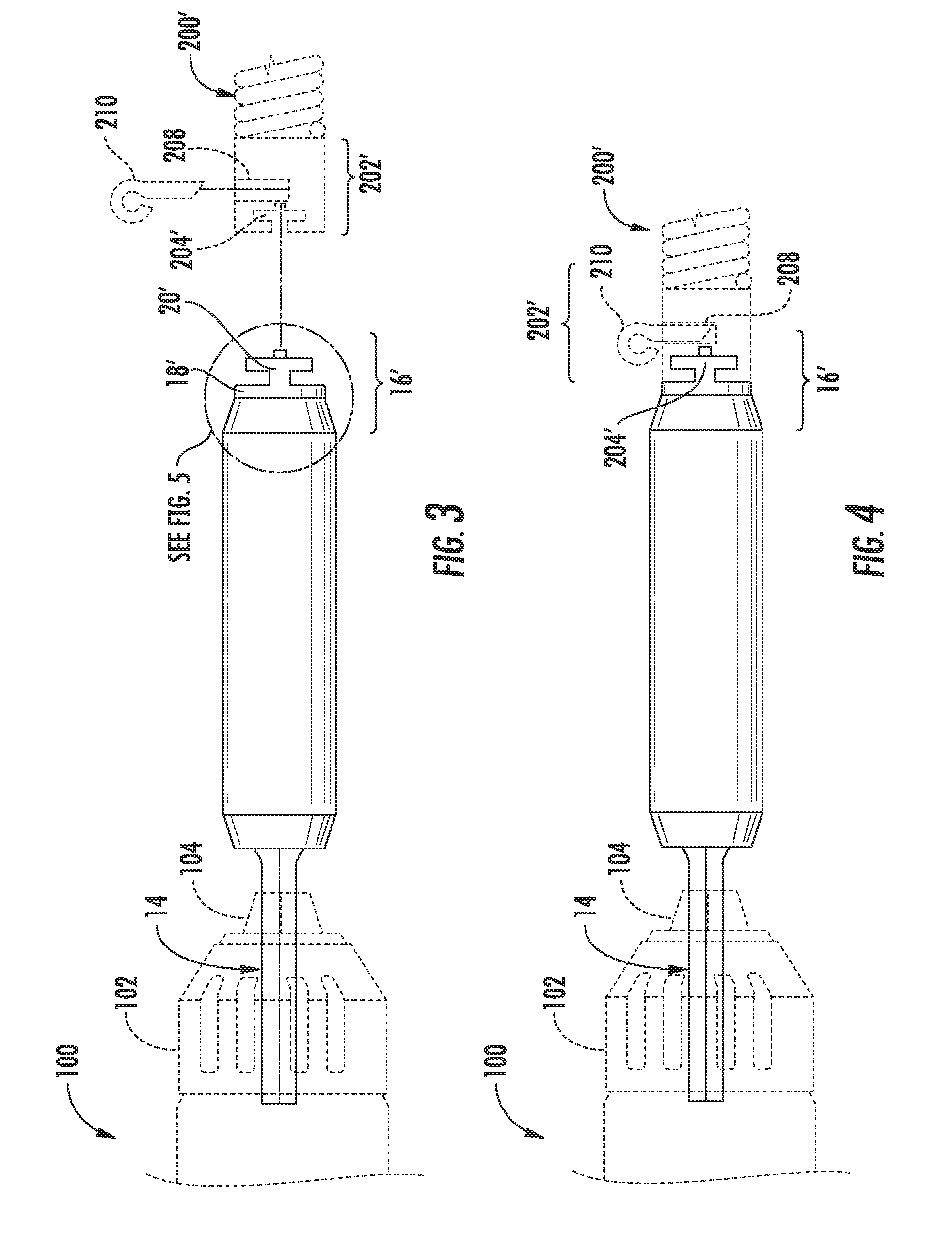
[0026]Referring now to FIGS. 3 through 6, a coupling means is depicted, namely coupler 16′. Coupler 16′ is adapted for mating engagement with a heavy duty cable 200′ having a RIDGID® brand female K-10 quick-connect coupling 202′, manufactured by Ridge Tool Company, attached to its proximal end. Female K-10 coupling 202′ includes a generally t-shaped (in cross-section) channel 204′ disposed transversely through its distal end for slidably receiving a similarly shaped male member of coupler 16′. Male coupler 16′ is similar or identical in design to the RIDGID® brand male K-10 quick-connect coupling manufactured by Ridge Tool Company and includes a disc-shaped base 18′ having a first side fixedly attached to, or integrally formed with, the second end 12b′ of grip 12′. The male member of coupler 16′ is comprised of a T-shaped transverse member 20′ projecting normal to the opposite side of base 18′. Transverse member 20′ includes an axial channel 28 disposed therethrough and in communica...


PUM


Abstract

A snake tool adaptor capable of coupling commercially available heavy duty drain cleaning cables and attachments normally associated with heavy electric drain cleaners with a portable rotary driving tool such as a hand-held drill. Adaptors of the subject invention include a hand grip having a proximal end terminating in a shank for operable attachment to a the chuck of a power drill, and a distal end terminating in coupling means for removable mating engagement with various heavy duty drain cleaning cables and their attachments normally associated with heavy electric drain cleaners.

Description

FIELD OF THE INVENTION[0001]The subject invention relates to the field of drain cleaning generally, and to an adapter for snake cables to permit coupling to handheld rotary power drills in particular.BACKGROUND OF THE INVENTION[0002]The term “drain cleaner” as used herein refers to a mechanical device used to unblock pipes or drains. Such drain cleaners can be classified in two categories, according to their intended use; handheld drain cleaners and electric drain cleaners. If a single sink, toilet, or tub or shower drain is clogged the first choice is normally a drain cleaner that can remove soft obstructions such as hair and grease clogs that can accumulate close to interior drain openings. Handheld drain cleaners or “augers” are intended for this purpose. If more than one plumbing fixture is dogged the first choice is normally a drain cleaner that can remove soft or hard obstructions along the entire length of the drain, from the drain opening through the main sewer drain to the ...

Claims


Application Information

Patent Timeline
IPC IPC(8): B08B9/04B08B9/00B08B9/027E03F9/00
CPCB08B9/027E03F9/005B08B9/00B08B9/045
Inventor KHONSARY, CYRUS
Owner KHONSARY CYRUS
Why Eureka
Try Eureka