Method for forming a package, a package and a package blank

a technology a package is applied in the field of forming a package, which can solve the problems of bending stiffness, plastic materials may shrink a little, and the shape of the rim may give technical problems, so as to reduce the bending stiffness

Inactive Publication Date: 2015-04-28
NEC CORP +1
View PDF19 Cites 3 Cited by
  • Summary
  • Abstract
  • Description
  • Claims
  • Application Information

AI Technical Summary

Benefits of technology

[0008]It is an object of the invention to provide a method for forming a package by moulding of a flat blank, which package will have an improved shape, i.e. a minimally distorted shape. It is also an object of the present invention to provide a package with improved shape. Another object with the present invention is to provide a package blank that can be used in the manufacture of a package with improved shape as a result.
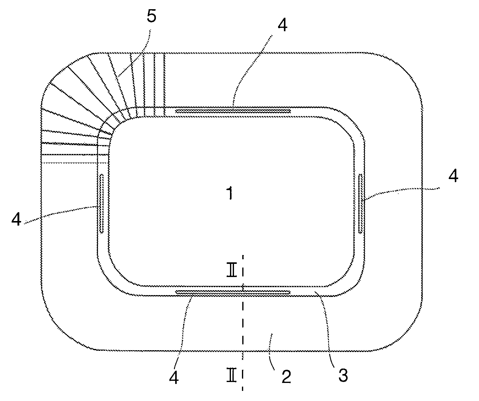
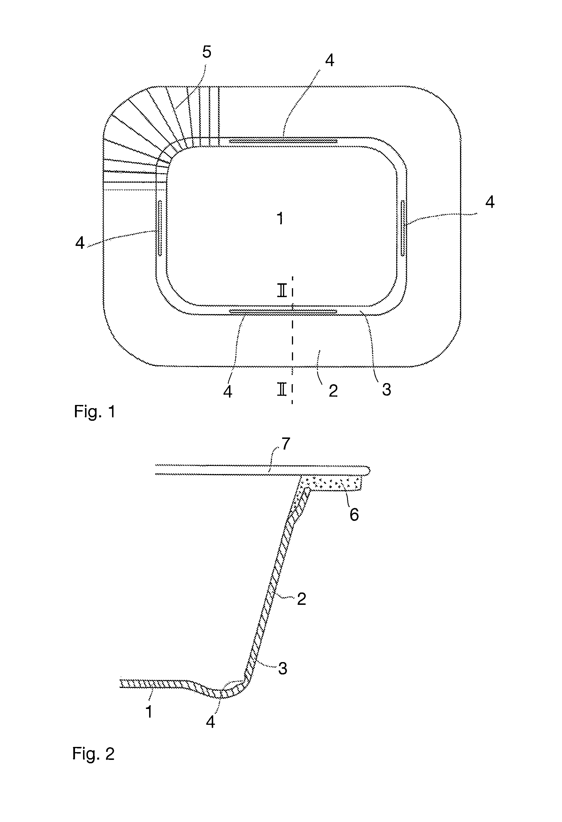
[0011]Thus, the at least one area of reduced bending stiffness will be situated in the moulded package in the area where the blank material is deformed due to moulding and is subjected to internal stresses which are caused by the tendency of the margin area of the moulded package to return to its original state. Providing the blank with at least one area of reduced bending stiffness will release the internal stress of the formed package.
[0013]By creating areas of reduced bending stiffness in those places of the blank which in the finished tray-shaped package will be in the transition zone between the bottom and side walls (i.e. areas where the blank material is bent in the forming process), it is possible to release the internal stresses which build up because of the above-mentioned memory effect of cardboard material and shrinkage of the rim. The deformation of the package can in this way be decreased or totally eliminated. These areas can be elongated areas of predetermined width that run parallelly to the straight sides of the blank. In a blank with general rectangular shape there is preferably four such areas: two in parallel with the shorter sides and two in parallel with the longer sides.
[0014]In practice the said areas can be made weaker by making the areas thinner compared with the rest of the blank material on their both sides. This can be performed by creasing, which reduces the thickness of the blank material. Creasing is an operation where the cardboard material is locally pressed to be flattened so that the board layers are separated and bending resistance decreased.
[0015]The areas of reduced bending stiffness do not by themselves cause bending or folding of the blank material during the moulding operation, but they, together with the rest of the blank material, conform to the bent shapes determined by the forming tool, and remain in these shapes as the areas will relieve the internal stresses. The width of these areas perpendicularly to the bending direction can be over 1 mm, preferably over 2 mm, and especially in the range of 2.5-4.0 mm. For example, by using multiple parallel creasing blades, a desired width of the area can be achieved. Narrow areas of reduced bending stiffness, which have the width of a conventional crease (around 0.7 mm) normally used for forming folds in cardboard material along predetermined lines, are not usually able to release internal stresses of the package in a satisfied way. However, the size of the area with reduced bending stiffness also depends on the size of the package. It might be sufficient to provide small packages with areas of reduced bending stiffness of below 1 mm, for example around 0.7 mm.
[0019]The present invention further relates to a package blank of planar shape wherein the blank comprises at least one area of reduced bending stiffness.

Problems solved by technology

Apart from being a visual defect, the curved shape of the rim may give technical problems during sealing of the lid to the tray package.
However some plastic materials may shrink a little when solidifying in comparison to the cardboard material, which creates internal forces and consequently curving of the rim.

Method used


Image

  • Method for forming a package, a package and a package blank
  • Method for forming a package, a package and a package blank

Examples


Embodiment Construction

[0023]The term “package” shall in this context mean either a closed package or an open package capable of taking a product to be packed and the package should be closable by a lid or similar closure.

[0024]The blank shown in FIG. 1 is a cardboard blank where the cardboard may be coated on one side, both sides or it may be uncoated. If the package made of the blank is for packaging food products, the coating on the blank may be a barrier material giving the blank barrier properties, for example a barrier against liquid, vapor, grease etc. The coating may consist of one layer or it can have two or several layers. Coatings used in cardboard packaging materials are widely known and they are not discussed in further detail in this context.

[0025]The blank is of general rectangular shape with successive straight sides and rounded corners at its outer edge, which is a widely used shape for tray-type containers. The blank has a middle portion 1 which is surrounded by a margin area 2 which is ...


PUM

PropertyMeasurementUnit
widthaaaaaaaaaa
widthaaaaaaaaaa
angleaaaaaaaaaa

Abstract

The present invention relates to a method for forming a package by moulding a cardboard blank in such a manner that a margin area (2) of the blank, surrounding a middle portion (1) of the blank, is bent upwards to form side walls of the package while the middle portion forms a bottom of the package. The cardboard blank prior to moulding is provided with at least one area (4) of reduced bending stiffness being located in a transition zone (3) between the side walls and the bottom. The package is moulded from the blank so that the at least one area (4) of reduced bending stiffness is located in the bended areas between the side walls and the bottom and extend in the running direction of the bend. The invention further relates to a package and a package blank that can be used for forming said package.

Description

[0001]This application is a U.S. National Stage under 35 U.S.C. §371 of International Application No. PCT / IB2011 / 053730, filed Aug. 25, 2011, which claims priority from Swedish Patent Application No. 1050874-5, filed Aug. 26, 2010.FIELD OF THE INVENTION[0002]The invention relates to a method for forming a package, wherein the package is moulded from a cardboard blank in such a manner that a margin area of the blank surrounding a middle portion of the blank is bent upwards to form side walls of the package while the middle portion forms the bottom of the package. The invention further relates to a package and a package blank that can be used for forming said package.BACKGROUND OF THE INVENTION[0003]A commonly used package for keeping food is a so-called tray package. The tray package is often closed hermetically with a lid. In order to attach the lid to the package, the edge of the package must be equipped with a horizontal rim or edge flange extending from the upper end of the side ...

Claims


Application Information

Patent Timeline
Patent Type & Authority Patents(United States)
IPC IPC(8): B65D1/40B65D1/00A47G19/02A47G23/06B29C59/02B31B1/00B31B50/59B65D1/34
CPCB65D1/40B31B1/00B65D1/34B31B2201/22B31B2201/6008Y10S229/93B31B50/59B31B50/62Y10T428/1303B31B50/142B31B50/743B31B2120/70B31B50/592
Inventor KARHU, TEEMUMYLLYS, TIMOPIRTTINIEMI, OLAVOJAVA, AIMOMAATTA, PAIVIJARVINEN, JALLIINA
Owner NEC CORP
Why Eureka
Try Eureka