
Method of manufacturing a bipolar transistor and bipolar transistor

a manufacturing method and technology of bipolar transistors, applied in the direction of transistors, electrical devices, semiconductor devices, etc., can solve the problems of limiting the usefulness of cmos transistors in rf applications, reducing the efficiency of cmos transistors, so as to reduce the impact of cmos technology on transistor performance, the effect of increasing the achievable dimension and reducing the cost of manufacturing

Active Publication Date: 2015-04-28
NXP BV
View PDF12 Cites 0 Cited by
  • Summary
  • Abstract
  • Description
  • Claims
  • Application Information

AI Technical Summary

Benefits of technology

The present invention provides a method for manufacturing a bipolar transistor that allows for an increase in the dimensions of the emitter without requiring additional process steps. By using a pillar with resistant to polishing, dishing of the emitter material during a planarizing polishing step can be largely avoided, thus extending the maximum dimensions of the emitter. The method further includes growing an epitaxial layer in the base window and forming sidewall spacers on the epitaxial layer prior to depositing the emitter material. The resulting transistor has a high-quality base formed inside the base window with the epitaxial layer, and the base / emitter stack can be extended compared to prior art devices. The transistor can also be surrounded by a plurality of pillars with no adverse effect on the transistor performance. Overall, the present invention allows for the production of bipolar transistors with larger dimensions and improved performance.

Problems solved by technology

However, the manufacture of integrated circuits (ICs) based on silicon bipolar transistor technology is more costly than for instance complementary metal oxide semiconductor (CMOS) ICs, and the downscaling of the device feature size is more easily achieved in CMOS technology.
However, the breakdown characteristics of CMOS transistors limit the usefulness of CMOS transistors in RF applications unless costly measures are implemented in the CMOS process to improve these characteristics.
Such costly measures typically prohibit the use of RF-CMOS technologies for manufacturing small volume devices such as analog mixed signal (AMS) devices.
The challenge that process developers face is that the number of alterations to the CMOS process should remain small whilst at the same time yielding good quality bipolar transistors that are capable of handling high frequency signals.
Nevertheless, the applicability of such CMOS technology-based bipolar transistors is not without problems.
It is particularly difficult to manufacture several identical bipolar transistors that have relatively wide emitter areas.
The main problem with establishing relatively large emitter areas, e.g. base windows having a width in excess of 2 μm is that during the planarizing of the emitter material deposited on the substrate with the purpose to fill the base window, not only excess emitter material is removed from outside the base window but also from inside the base window.
This is known as dishing, and is particularly problematic when using chemical mechanical polishing (CMP).

Method used


Image

  • Method of manufacturing a bipolar transistor and bipolar transistor
  • Method of manufacturing a bipolar transistor and bipolar transistor
  • Method of manufacturing a bipolar transistor and bipolar transistor

Examples


Embodiment Construction

[0021]Embodiments of the invention are described in more detail and by way of non-limiting examples with reference to the accompanying drawings, wherein

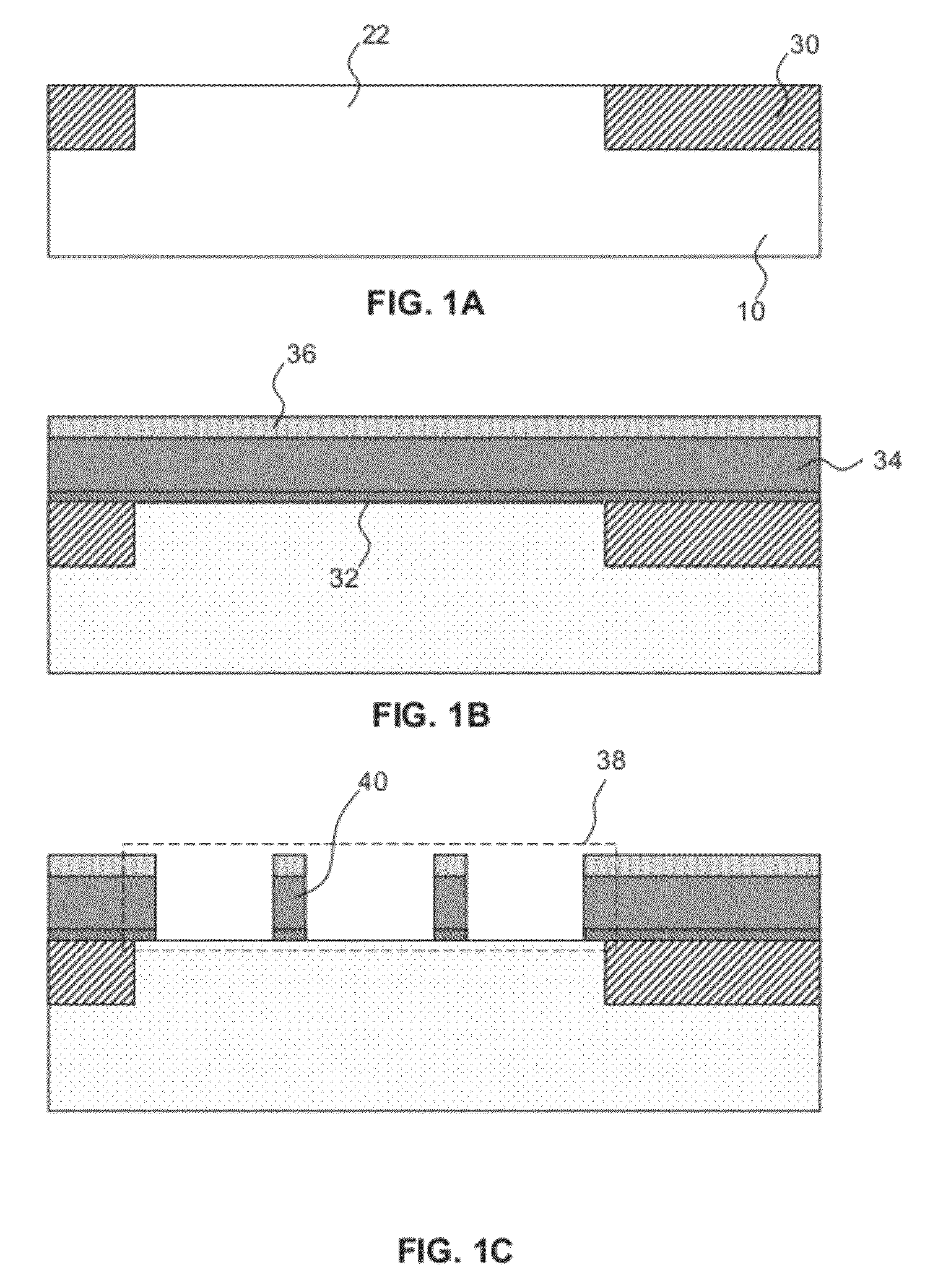
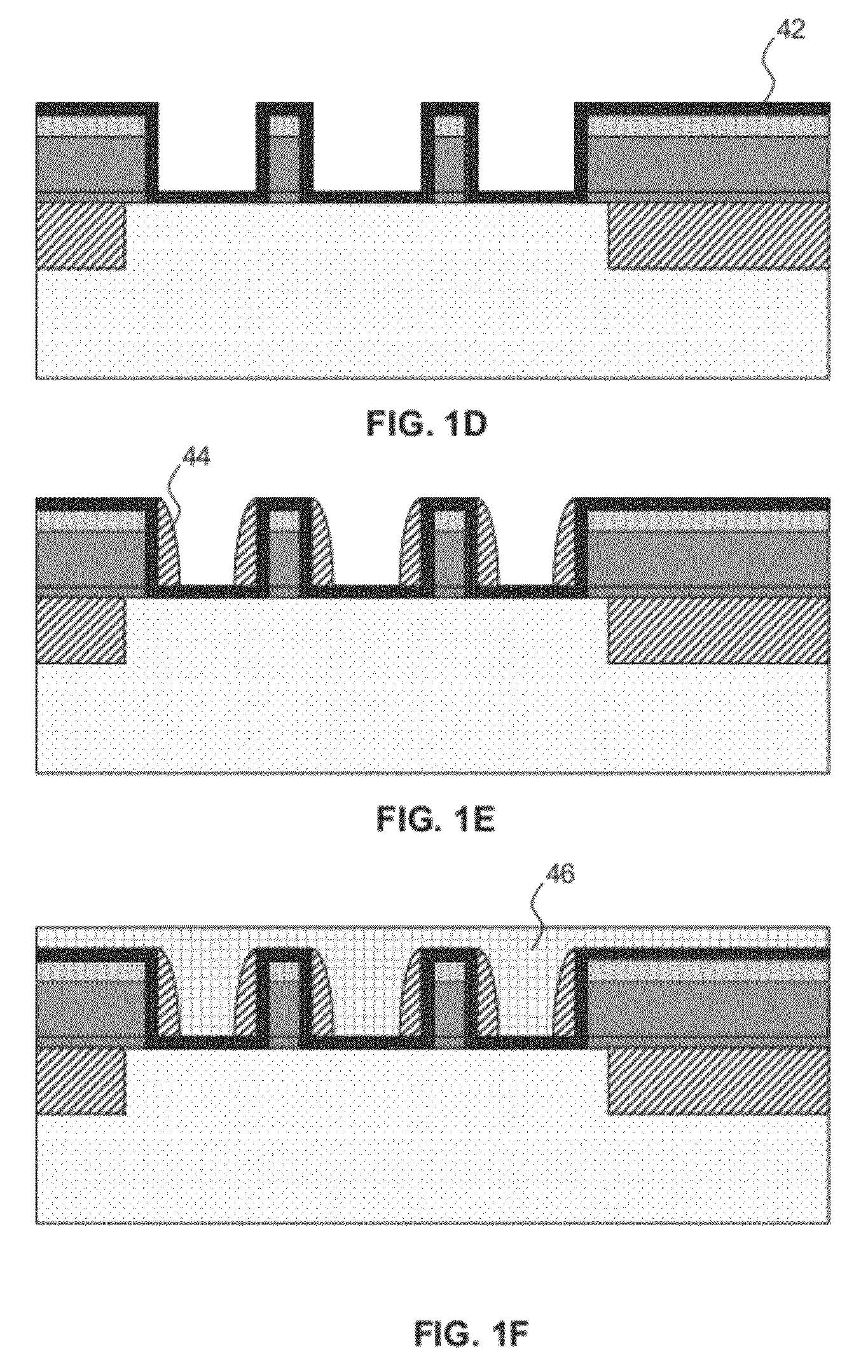
[0022]FIGS. 1A-1G schematically depicts an embodiment of the method of the present disclosure; and

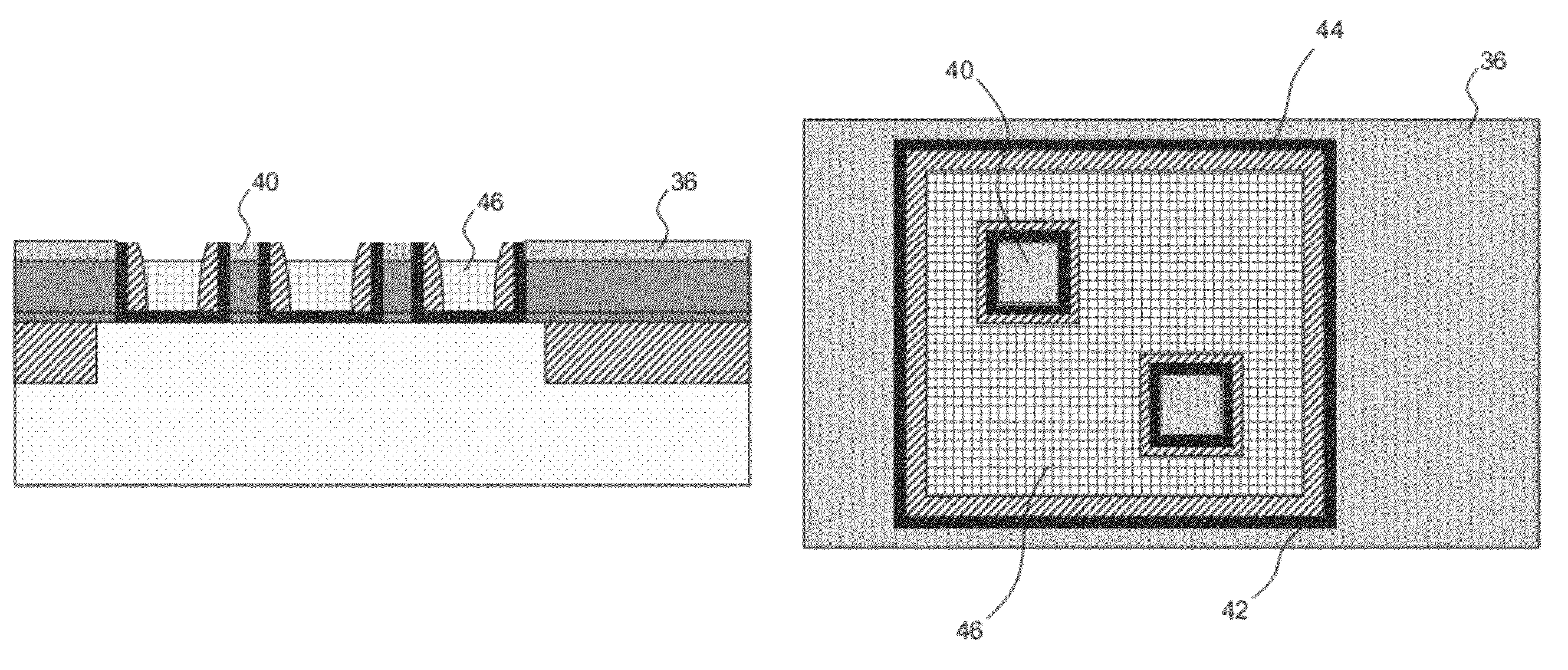
[0023]FIG. 2 schematically depicts a top view of a bipolar transistor according to an embodiment of the present invention.

DETAILED DESCRIPTION OF THE DRAWINGS

[0024]It should be understood that the Figures are merely schematic and are not drawn to scale. It should also be understood that the same reference numerals are used throughout the Figures to indicate the same or similar parts.

[0025]FIGS. 1A-1G show a first embodiment of the method of the present invention. In FIG. 1A, a substrate 10 is provided in which an active region 22 is formed. The substrate 10 may be any suitable substrate, such as a silicon substrate and so on. The substrate 10 typically at some stage comprises a collector region (not shown), which may be formed in any sui...


PUM


Abstract

Consistent with an example embodiment, there is method of manufacturing a bipolar transistor comprising providing a substrate including an active region; depositing a layer stack; forming a base window over the active region in said layer stack; forming at least one pillar in the base window, wherein a part of the pillar is resistant to polishing; depositing an emitter material over the resultant structure, thereby filling said base window; and planarizing the deposited emitter material by polishing. Consistent with another example embodiment, a bipolar transistor may be manufactured according to the afore-mentioned method.

Description

[0001]This application claims the priority under 35 U.S.C. §119 of European patent application no. 10192803.4, filed on Nov. 26, 2010, the contents of which are incorporated by reference herein.FIELD OF THE INVENTION[0002]The present invention relates to a method of manufacturing a bipolar transistor comprising providing a substrate including an active region; depositing a layer stack; and forming a base window at least partially over the active region in said layer stack.[0003]The present invention further relates to a bipolar transistor manufactured in accordance with such a method.BACKGROUND OF THE INVENTION[0004]Nowadays, many electronic devices incorporate functionality that operates at radio frequencies, such as mobile communication devices. The implementation of such functionality in a cost-effective manner is far from trivial. It is well-known that bipolar transistors are particularly suitable for handling signals in the radio frequency (RF) domain. However, the manufacture ...

Claims


Application Information

Patent Timeline
Patent Type & Authority Patents(United States)
IPC IPC(8): H01L29/732H01L21/8249H01L27/06H01L29/08H01L29/10H01L29/66
CPCH01L21/8249H01L27/0623H01L29/0813H01L29/1004H01L29/66287H01L29/7322
Inventor GRIDELET, EVELYNEVANHOUCKE, TONYDONKERS, JOHANNES JOSEPHUS THEODORUS MARINUSMERTENS, HANSDURIEZ, BLANDINE
Owner NXP BV
Learn More