
Apparatus and method for processing signals

a signal and apparatus technology, applied in the direction of dc level restoring means or bias distorting correction, transmission, sensors, etc., can solve problems such as general instability, and achieve the effect of improving signal quality

Inactive Publication Date: 2015-04-28
TWENTE MEDICAL SYST INT
View PDF5 Cites 0 Cited by
  • Summary
  • Abstract
  • Description
  • Claims
  • Application Information

AI Technical Summary

Benefits of technology

The present invention aims to provide an improved reference amplifier that can achieve gains of over 500× and provide improved signal quality. The apparatus is relatively energy-efficient, requiring relatively little operating power. It can be made economically and compactly. It can also compensate well offsets and remove common signal components from the signals. It prevents dc-signal offsets in the primary references amplifier stage and optimizes the amplifier signal output power. It can process low frequency input signals without the need for high-pass filters. Overall, the apparatus improves the accuracy and quality of the signal processing.

Problems solved by technology

A sensor-offset signal, in particular an electrode offset (the third component in an input signal) can have varying amplitudes, and is generally not stable.

Method used


Image

  • Apparatus and method for processing signals
  • Apparatus and method for processing signals
  • Apparatus and method for processing signals

Examples


Embodiment Construction

[0043]In this application, identical or corresponding features are indicated with identical or corresponding reference numerals.

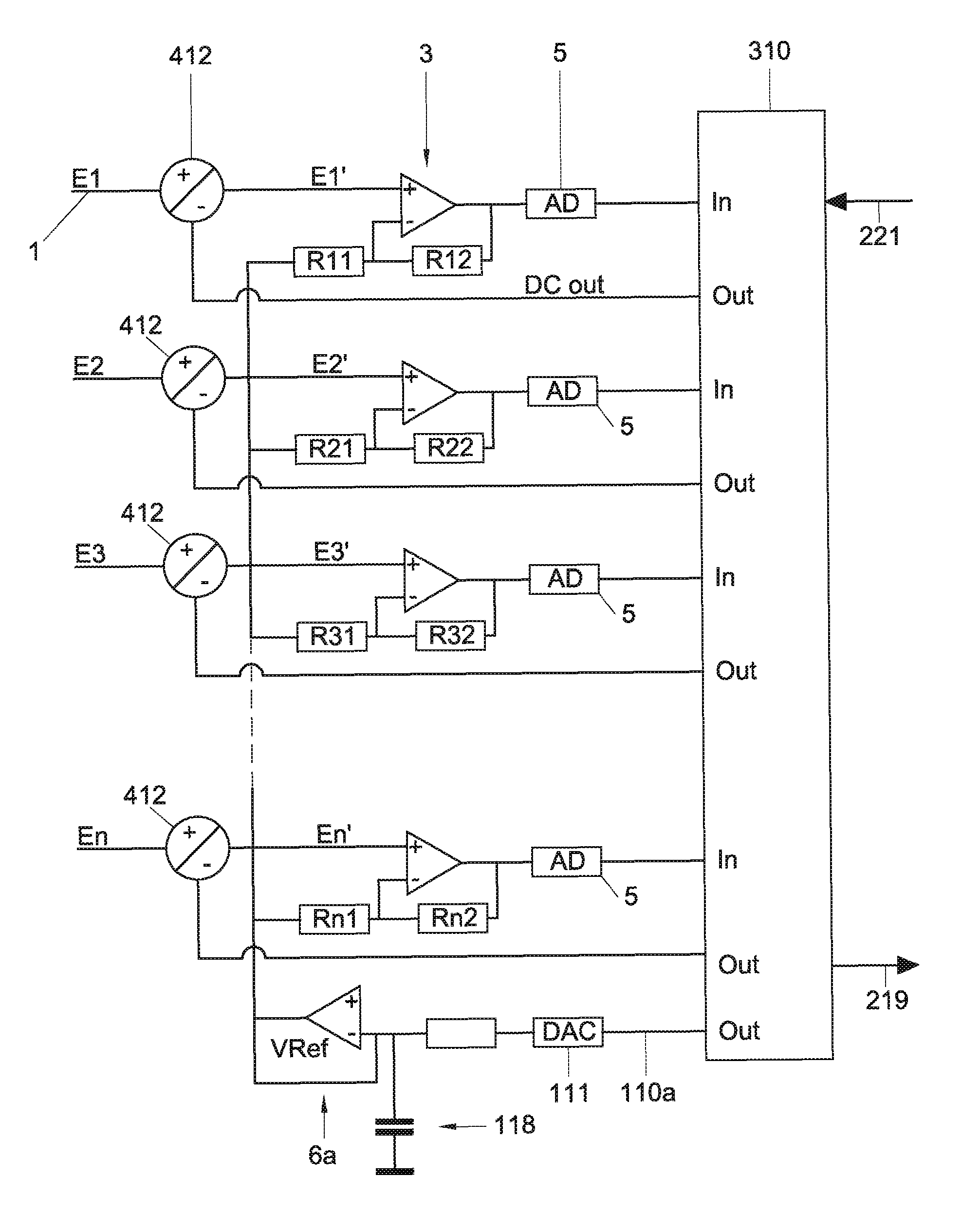
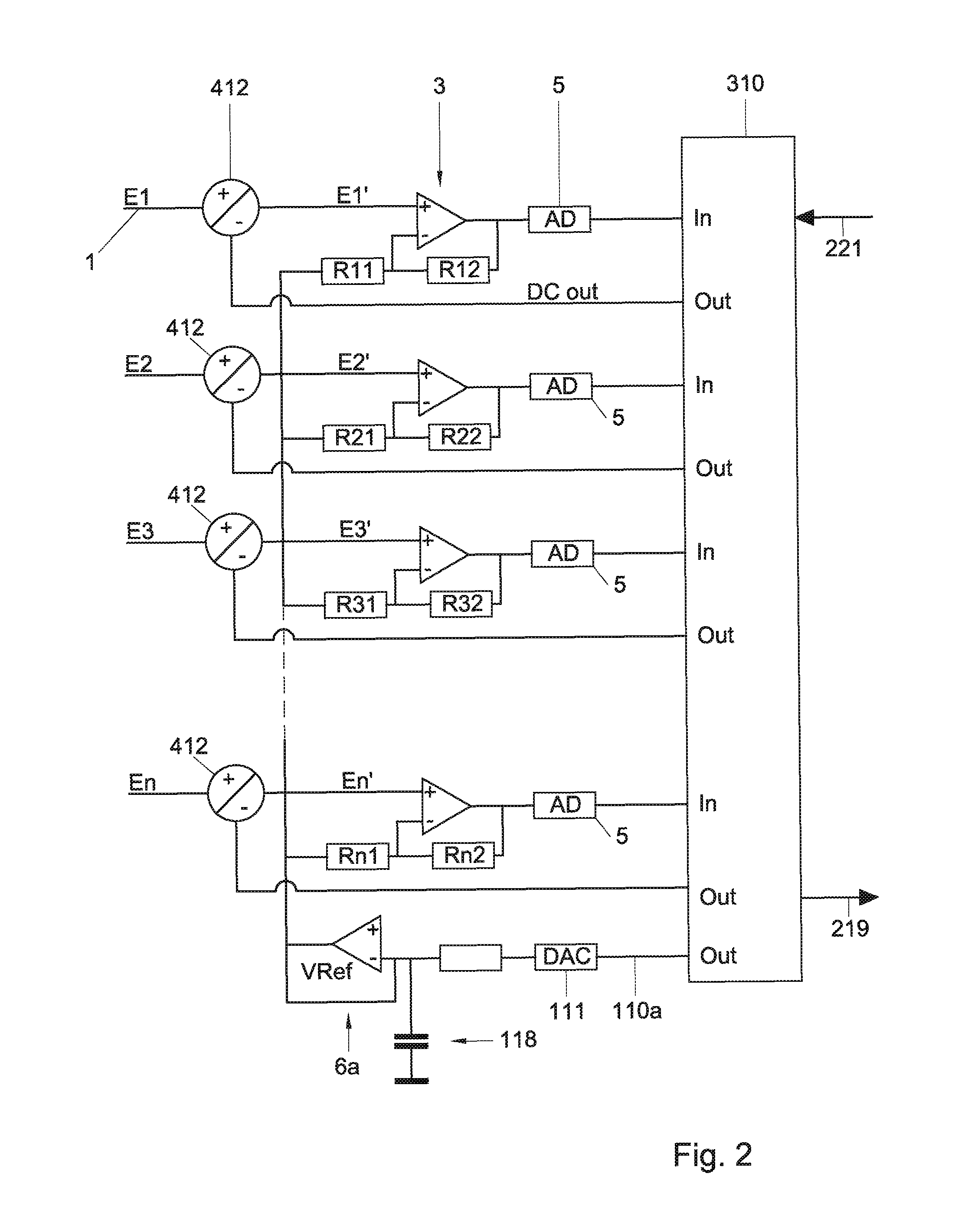
[0044]FIG. 2 shows a first non-limiting embodiment of an apparatus according to the invention.

[0045]The apparatus, in particular, is a DC reference amplifier. The apparatus represented in FIG. 2, which serves for processing signals, in particular physiological measuring signals supplied through sensors (not represented), is provided with several (N) channels with N signal inputs 1 for receiving input signals, which input signals E1, E2, E3, . . . , En (with n being 1, 2, 3, . . . , N) each comprise a specific signal component and a signal component common to all input signals. Furthermore, for a particular period of time, one or more input signals E1, E2, E3, . . . , En may contain sensor related offset signal parts, as is described hereinabove.

[0046]Preferably, the different channels (also called signal paths) may be designed in the same manner. Each chann...


PUM


Abstract

An apparatus for processing signals, in particular physiological measuring signals, is provided with a number of channels with main signal inputs for receiving input signals. Each of the input signals has a specific signal component and a signal component common to all input signals. Each channel is provided with an impedance transforming input amplifier. The apparatus supplies a respective input signal to the first input of each input amplifier and an analog reference signal, which is equal for all channels, to the second input. The apparatus includes a digital signal processor and one or more analog-digital converters for supplying the signals provided by the input amplifiers to the digital signal processor. The signal processor converts signals received from the one or more analog-digital converters at least into one or more output signals.

Description

RELATED APPLICATIONS[0001]This application is the U.S. National Phase of International Application No. PCT / NL2013 / 050130, filed Mar. 1, 2013, designating the U.S. and published in English as WO 2013 / 133697 on Sep. 12, 2013 which claims the benefit of Dutch Patent Application No. 2008441 filed Mar. 9, 2012.BACKGROUND OF THE INVENTION[0002]1. Field of the Invention[0003]The invention relates to an apparatus for processing signals, in particular physiological measuring signals, for instance EEG-signals (electroencephalogram signals), wherein the apparatus is provided with a plurality of channels with signal inputs for receiving input signals, which input signals each comprise a specific signal component and a signal component common to all input signals (also called a “common mode” signal), wherein each channel is provided with an impedance transforming input amplifier, wherein the apparatus is configured for supplying to a first input of each input amplifier a respective signal and to...

Claims


Application Information

Patent Timeline
IPC IPC(8): H04B1/38H04L5/16A61B5/04A61N1/365H04B1/16H04L25/06
CPCH04L25/061H04B1/16A61B5/04004A61N1/36521H03F3/45968H03F3/45475H03F3/68H03F2200/261H03F2203/45138A61B5/30
Inventor PEUSCHER, JAN HENDRIK
Owner TWENTE MEDICAL SYST INT
Learn More