
Brain electrode lead anchoring device

a technology of lead anchoring device and brain electrode, which is applied in the direction of head electrode, internal electrode, therapy, etc., can solve the problems of dislodgement of the electrode from the desired stimulation site, discomfort or other complication of the patient, unexpected clinical consequences, etc., and achieve the effect of less protruding and less discomfort for the patien

Active Publication Date: 2015-04-28
SCENERAY
View PDF16 Cites 1 Cited by
  • Summary
  • Abstract
  • Description
  • Claims
  • Application Information

AI Technical Summary

Benefits of technology

This invention is a device that can safely and securely attach a brain lead to the skull and keep it in place during surgery. It prevents the lead from moving around during the procedure, which could affect its placement. The device is easy to use and is less uncomfortable for the patient than previous versions. The invention has a unique design featuring a septum that prevents the lead from dropping out of the device during insertion. Overall, this invention provides a reliable and effective solution for attaching brain leads to the skull.

Problems solved by technology

However, the disadvantage of this method is obvious: the engagement between the plug and socket during the insertion inevitably brings the lead along with the plug's downward movement, thus causes the dislodgement of the electrodes from the desired stimulation site.
Such dislodgement may result in unexpected clinical consequences.
Such thick foreign material on the cranium will cause discomfort or other complication to the patient.

Method used


Image

  • Brain electrode lead anchoring device
  • Brain electrode lead anchoring device
  • Brain electrode lead anchoring device

Examples


first embodiment

The First Embodiment

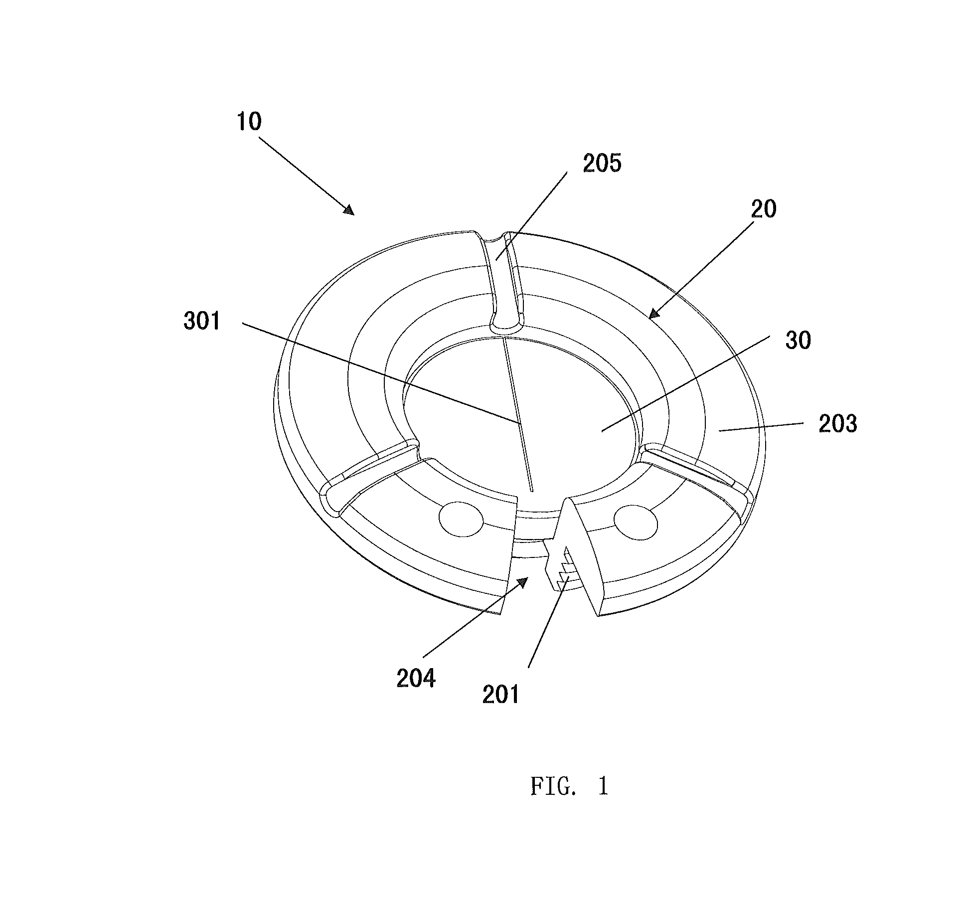
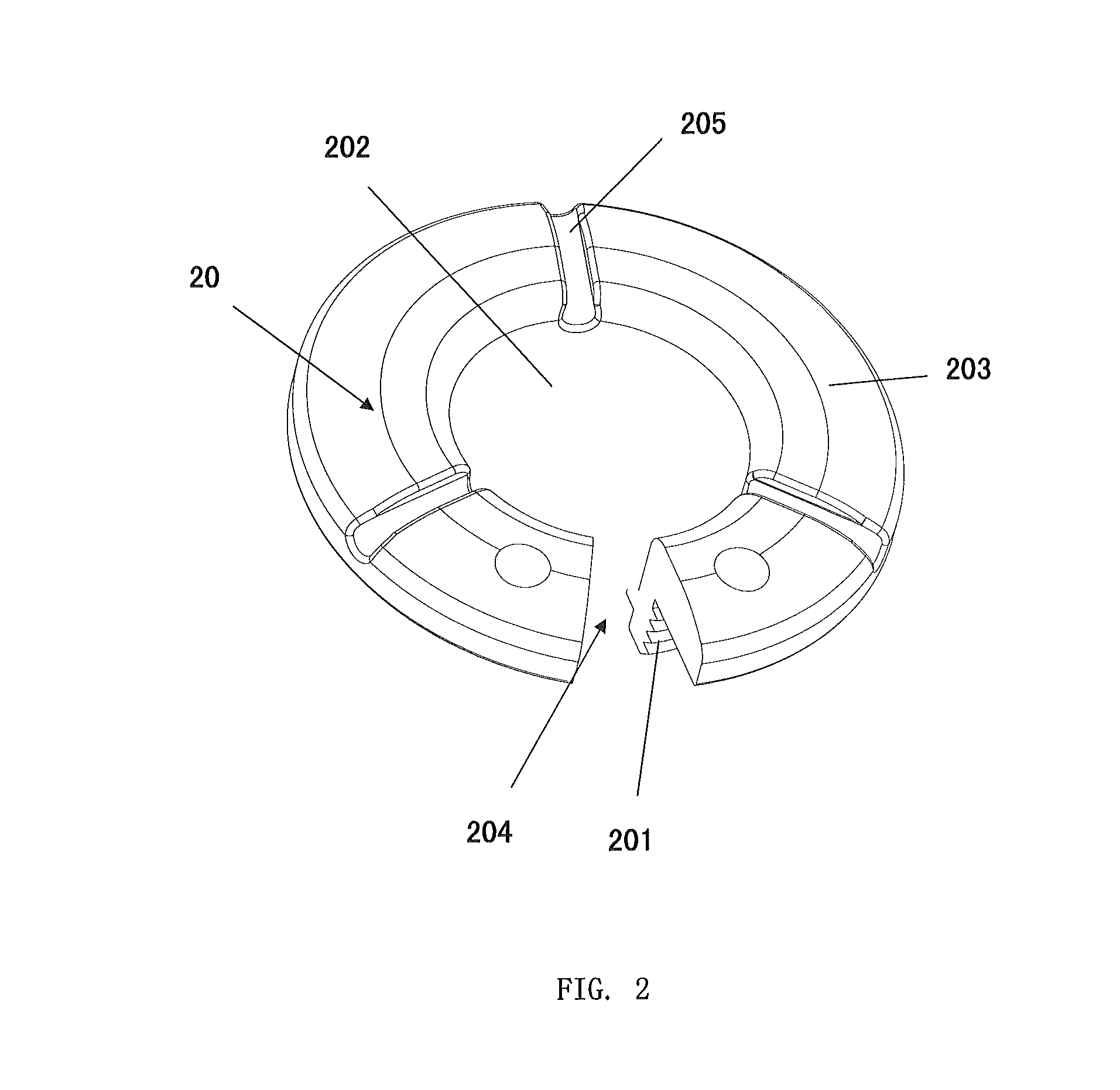
[0039]As shown in FIGS. 1-5, a device for anchoring brain leads 10 comprises a cranial ring 20 and a cranial septum 30. The anchoring ring 20 comprises a circular base 201 and a flange portion 203 joining together where the inner walls form an aperture 202 defining a passage of a lead and outer walls engage with a burr hole to secure said ring 20 to the cranium. The septum 30 is contained within the aperture 202 of the anchoring ring 20, comprising a slit 301 in its center to allow the brain lead to pass through.

[0040]In this embodiment, the slit 301 is a through-slit through which the clinician passes a trocar into the brain of patient for use. Alternatively, the slit can be shallow slit or deep slit. As shown in FIGS. 6 and 7, when in use, the clinician just need to use the trocar to pierce the shallow slit or deep slit so as to insert the brain lead to a pre-calculated depth through the inner hole of the trocar.

[0041]The through-slit and the deep / shallow slit ...

second embodiment

The Second Embodiment

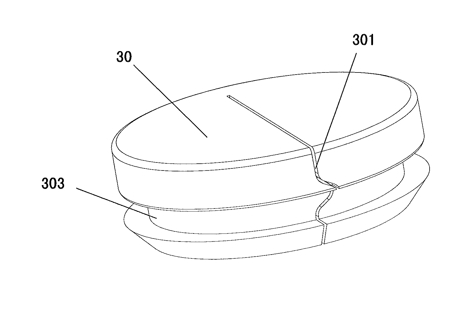
[0047]As shown in FIGS. 8 to 11, the second embodiment differs from the first one in the slit 301. According to the second embodiment, one end of the slit 301 extends to the edge of the outside wall of the cranial septum 30 to form an edge-engaging through slit. However, the use of the device for anchoring a brain lead is different from that according to the first embodiment.

[0048]When in use, the cranial ring 20 is inserted to the cranial burr hole of the patient. The trocar is then inserted in place after cranial ring 20 mates well with the burr hole. Then, the trocar is anchored by a dedicated clamp while the nerve stimulation lead is inserted to a pre-calculated depth through the inner hole of the trocar. After the clinicians completes the adjustment and test, as shown in FIG. 7, the slit 301 of the cranium septum 30 is expanded sideways by hand to form a notch. The trocar which is aligned in position and contains the lead is clamped within the cranium septu...

third embodiment

The Third Embodiment

[0049]As shown in FIG. 12, the slit 301 of the cranium septum 30 in this embodiment is an edge-engaging curve slit rather than the “-” shaped edge-engaging straight slit. The operational steps for the clinicians are substantially the same as those in the second embodiment. When the cranium septum 30 is inserted into the lead aperture 202 of the cranial ring 20, the cranium septum 30 and the cranial ring 20 are well mated by the mating between the recessed portion 303 of the cranium septum 30 and the protrusion 206 of the ring 20. Meanwhile, the edge-engaging curve slit makes it easy to determine whether the cranium septum 30 is inserted in position.


PUM


Abstract

Disclosed is a device for anchoring a brain lead that includes an anchoring ring with a circular base and a flange joining together where the inner walls form an aperture define a passage of a lead. Outer walls engage with a burr hole to secure the ring to the cranium, and a septum is contained within the aperture of the anchoring ring. Because the septum is already placed in the aperture when the trocar is removed from the brain, the body of the brain lead is immediately clamped by the elastic material of the septum while the tip of trocar is removed from the slit of septum. Friction between the lead body and the elastic material prohibits any movement of the lead caused by handling.

Description

RELATED APPLICATIONS[0001]This application is a 35 U.S.C. §371 national phase application of PCT Application PCT / CN2011 / 083482, filed May 12, 2011, which claims priority to CN 201010588332.8, filed Dec. 15, 2010. The entire content of each of these applications is incorporated herein by reference.TECHNICAL FIELD[0002]The present invention generally relates to the field of implanted medical system, and more particularly relates to a device for anchoring brain lead or other catheter or the like onto cranium in an implantable medical device system.BACKGROUND[0003]An implantable medical device system typically comprises an implantable nerve stimulation system, an implantable cardiac stimulation system (known as cardiac pacemaker), and an implantable medication infusion system, where the implantable nerve stimulation system comprises a deep brain stimulation (DBS), an implantable cortical nerve stimulation (CNS), an implantable spinal cord stimulation (SCS), an implantable sacral nerve s...

Claims


Application Information

Patent Timeline
Patent Type & Authority Patents(United States)
IPC IPC(8): A61N1/05
CPCA61N1/0539
Inventor YIN, WEIZHONG
Owner SCENERAY
Learn More