Cavity filter with high flatness feedback

a filter and feedback technology, applied in the field of cavity filter, can solve the problems of instability of transmission signal at the stop-band frequency, not easy to create a cavity, and important full bandwidth utilization, so as to improve the quality of the signal received, improve the stop-band flatness, and improve the effect of stop-band flatness

Inactive Publication Date: 2015-05-05
UNIVERSAL MICROWAVE TECH INC
View PDF3 Cites 6 Cited by
  • Summary
  • Abstract
  • Description
  • Claims
  • Application Information

AI Technical Summary

Benefits of technology

[0008]The present invention has been accomplished under the circumstances in view. It is one object of the present invention to provide a cavity filter, which comprises two series of resonance chambers bilaterally connected between an antenna port and two opposing signal input / output ports in a resonant space to provide a cross-coupling feedback, getting better stop-band flatness and improving the quality of the signal received by the signal receiver using the cavity filter.
[0009]To achieve this and other objects of the present invention, a cavity filter comprises a base member and a cover member. The base member comprises a resonant space, an antenna port disposed at the center of the resonant space, two signal input / output ports respectively disposed at two distal ends of the resonant space for signal input / output, two series of resonance chambers respectively and connected between the signal input / output ports and the antenna port, a channel cut through each partition plate between the first and last resonance chambers and between the second and last second resonance chambers, and a signal guide-way connected between each two adjacent resonance chambers of each of the two series of resonance chambers. The cover member is covered on the base member, carrying multiple frequency-adjusting rods of a frequency adjustment device for tuning by the user to adjust the frequency and bandwidth in the resonant space subject to the desired frequency range and to adjust the reverse coupling effects in the resonant space for enabling the series of resonance chambers and the respective channels to provide a cross-coupling feedback. Thus, usable feedback frequency components can be obtained from attenuated signal components to compensate for stop-band attenuation components, and smaller frequency components can be provided to get better stop-band flatness. Therefore, the cavity filter greatly improves the quality of the signal received by the signal receiver (such as wireless communication base station, satellite communication equipment or microwave transmitter / receiver antenna) that is used with the cavity filter, enhancing signal transmission stability and avoiding interference of noises.
[0010]Further, according to the preferred embodiment of the present invention, each series of resonance chambers ranges from 1st to 9th. Further, a partition plate is respectively set between the 1st resonance chamber and 9th resonance chamber and between the 2nd resonance chamber and 8th resonance chamber of each of the two series of resonance chambers, and a channel cut through each partition plate in communication between the 1st resonance chamber and 9th resonance chamber or between the 2nd resonance chamber and 8th resonance chamber of each associating series of resonance chambers. Further, a signal guide-way connected between each two adjacent resonance chambers of each of the two series of resonance chambers. Thus, the cavity filter can provide enhanced cross-coupling effects, enhancing signal feedback.

Problems solved by technology

However, due to limited wireless communication channels, full bandwidth utilization is quite important.
However, it is not easy to create a cavity that effectively removes noises and achieves excellent channel-to-channel isolation.
However, a cavity filter cannot completely isolate the stop-band energy, causing instability of transmission signal at the stop-band frequency.
According to this design, when a signal goes through the resonance chambers A01, attenuated signal components will be diffused to interfere with the performance of the cavity filter, affecting signal receiving or transmitting stability.
This wide flatness range causes signal instability.

Method used


Image

  • Cavity filter with high flatness feedback
  • Cavity filter with high flatness feedback
  • Cavity filter with high flatness feedback

Examples


Embodiment Construction

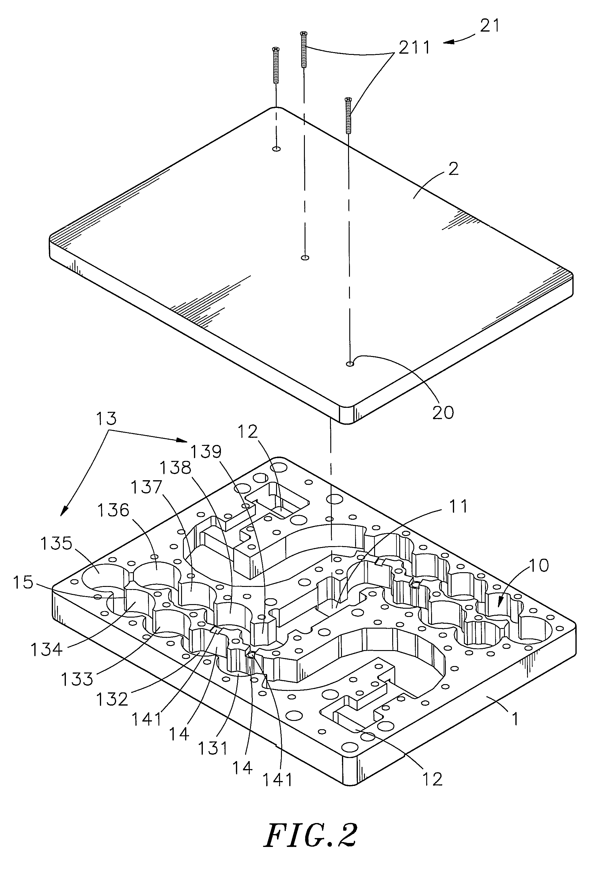
[0018]Referring to FIGS. 1˜4, a cavity filter in accordance with the present invention is shown comprising a base member 1 and a cover member 2.

[0019]The base member 1 defines therein a resonant space 10, an antenna port 11 disposed at the center of the resonant space 10, two signal input / output ports 12 respectively disposed at two distal ends of the resonant space 10 for signal input / output, two series of resonance chambers 13 respectively connected between the signal input / output ports 12 and the antenna port 11, each series of resonance chambers 13 ranging from 1st to 9th, a partition plate 14 respectively set between the 1st resonance chamber 131 and 9th resonance chamber 139 and between the 2nd resonance chamber 132 and 8th resonance chamber 138 of each of the two series of resonance chambers 13, a channel 141 cut through each partition plate 14 in communication between the 1st resonance chamber 131 and 9th resonance chamber 139 or between the 2nd resonance chamber 132 and 8th...


PUM


Abstract

A cavity filter having two series of resonance chambers bilaterally connected between an antenna port and two opposing signal input / output ports in a resonant space therein, each series of resonance chambers having the last resonance chamber thereof connected to the antenna port and the first resonance chamber thereof connected to the respective signal input / output port and kept in communication with the associating last resonance chamber through one respective channel and the second resonance chamber thereof kept in communication with the last second resonance chamber thereof through one respective channel to provide cross-coupling feedback, getting better stop-band flatness and improving signal quality.

Description

[0001]This application is a Continuation-In-Part of application Ser. No. 13 / 115,643, filed on May 25, 2011, for which priority is claimed under 35 U.S.C. §120, the entire contents of which are hereby incorporated by reference.BACKGROUND OF THE INVENTION[0002]1. Field of the Invention:[0003]The present invention relates to electronic signal filter technology and more particularly, to a cavity filter, which has two series of resonance chambers bilaterally connected between an antenna port and two opposing signal input / output ports in a resonant space to provide a cross-coupling feedback, getting better stop-band flatness and improving the quality of the signal received by the signal receiver using the cavity filter.[0004]2. Description of the Related Art:[0005]Following fast development of communication technology, many advanced wired and wireless signal transmitting and receiving equipment have been created and are widely used in different fields. However, due to limited wireless com...

Claims


Application Information

Patent Timeline
Patent Type & Authority Patents(United States)
IPC IPC(8): H01P1/213H01P1/205H01P1/208
CPCH01P1/2136H01P1/208H01P1/205
Inventor CHENG, WEIHSU, WEI-HONGCHANG, TSUNG-HAN
Owner UNIVERSAL MICROWAVE TECH INC
Why Eureka
Try Eureka