
Pitcher training apparatus and method using a ball with an embedded inertial measurement unit

a technology of inertial measurement and training apparatus, which is applied in the field of sports training equipment, can solve the problems of inability to train operators skilled in both, inability to accurately measure the inertial motion of the ball, etc., and achieves the effects of low cost, minimal intrusion, and high portability

Active Publication Date: 2015-05-19
RGT UNIV OF MICHIGAN
View PDF74 Cites 37 Cited by
  • Summary
  • Abstract
  • Description
  • Claims
  • Application Information

AI Technical Summary

Benefits of technology

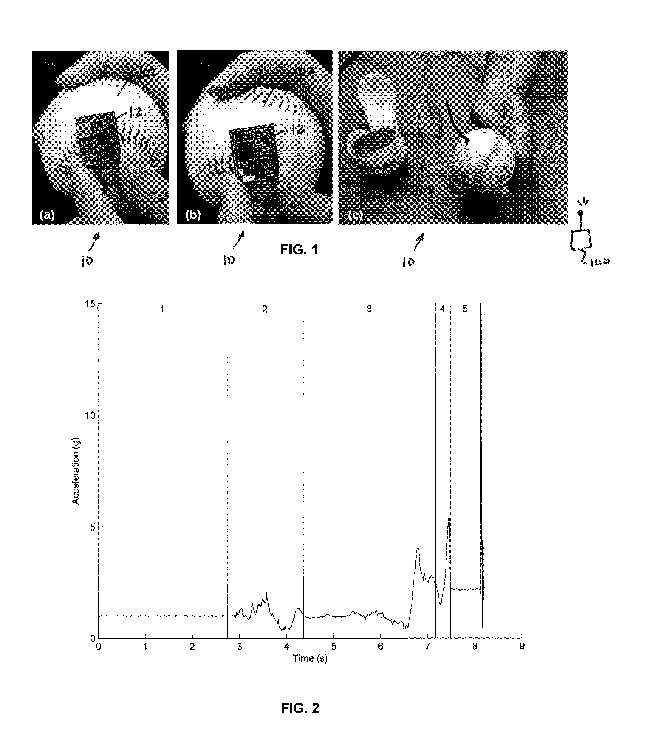
[0007]The present teachings address these shortcomings by presenting a highly miniaturized wireless IMU that is small and light enough to be embedded within a baseball (FIG. 1). The resulting design yields a low cost, highly portable and minimally intrusive approach for measuring the kinematics of the baseball during the pitching motion. While some ball spin rates remain outside the measurement range of most of today's technology for angular rate gyros, future advances of the present teachings, together with other methods, will allow ubiquitous application of the methods presented herein in the future.
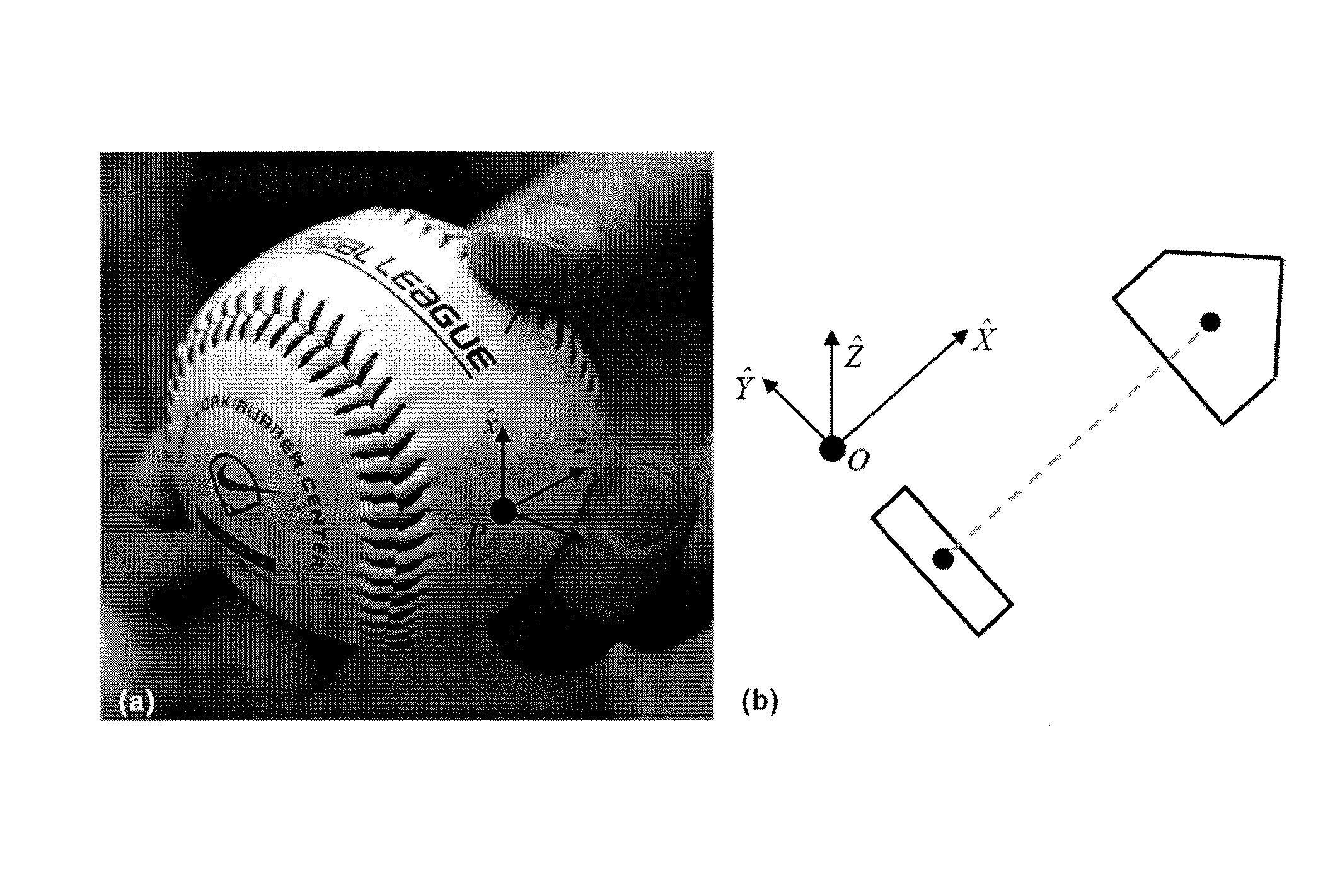
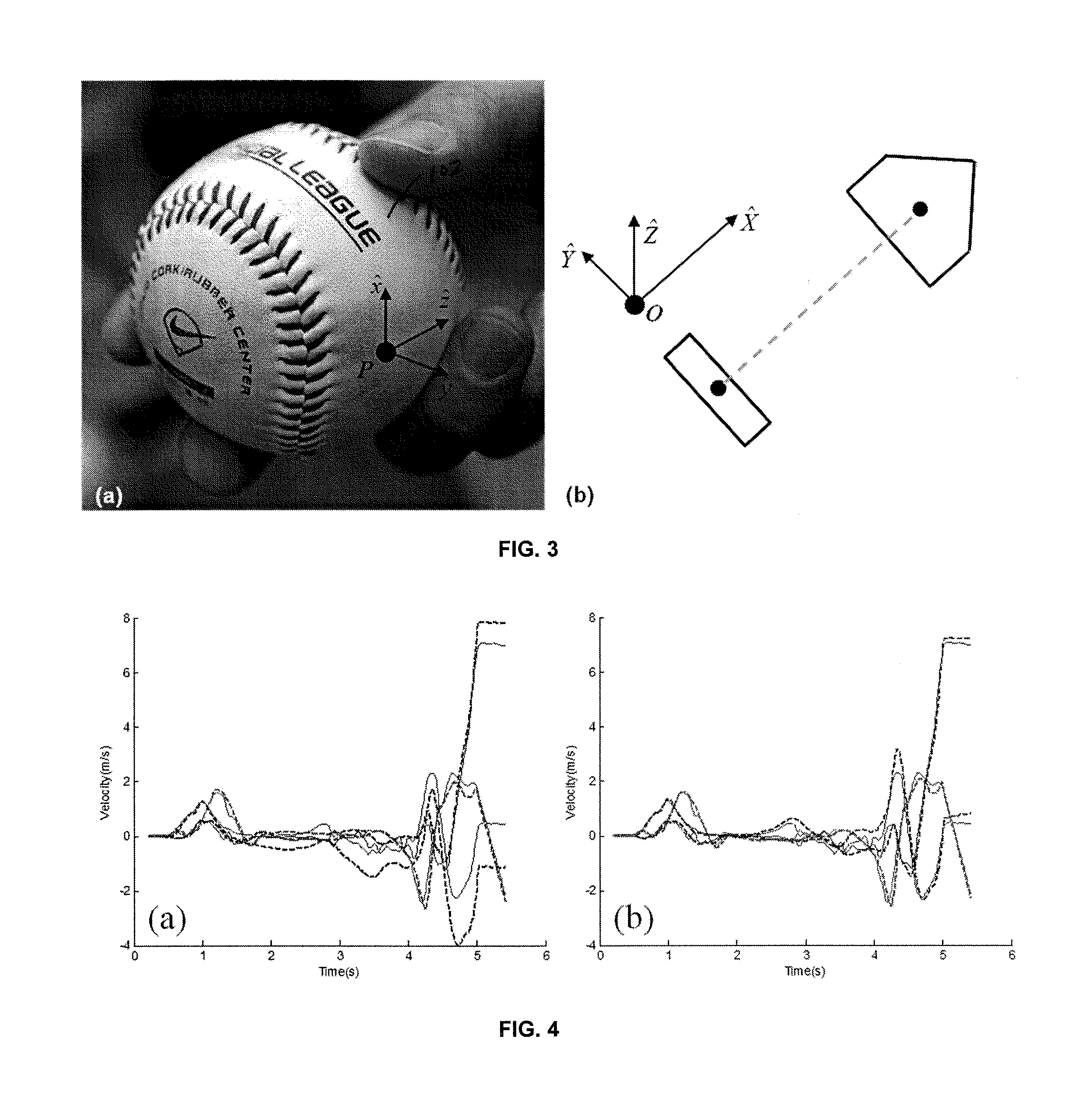
[0047]To demonstrate the accuracy of the IMU 12 calculated ball velocity, the three-dimensional ball velocity as determined via the aforementioned method is compared to the velocity as determined using a 10-camera high speed motion analysis system (VICON) calibrated such that marker errors for all ten cameras were less than 0.250 mm. The baseball, with embedded IMU, was completely coated in reflective tape and its 3-D position was measured by the VICON system at a frequency of 100 Hz. The ball 102's position data was smoothed using a 6-point moving average technique and then differentiated to determine the ball 102's velocity to minimize the effect of measurement noise on the calculation.
[0056]The images of baseball release conditions reported in FIG. 5, for pitches thrown with modest linear and angular speed, confirm expected trends. FIGS. 5A & 5B illustrate the release conditions for a fastball and change-up, respectively. These two pitches are thrown largely with backspin which will cause an aerodynamic lift force. Additionally, a small amount of lateral break develops due to the small side spin components of the angular velocity. In contrast, FIG. 5C shows that a curveball is released with largely top spin, and the resulting aerodynamic force accelerates the ball 102 downwards. Like the fastball and change-up, small side-spin components create additional but small lateral break. Finally, FIG. 5D shows the release conditions for a slider which has largely side spin, but also a small top spin component. The side spin induces a large lateral break, while the topspin induces a small drop. The position of the spin axis of the ball 102 relative to the velocity of the ball 102 center at release provides the essential information needed to evaluate whether the desired type of pitch is thrown correctly, to what degree the pitcher achieves that type of pitch, and also how consistently it is thrown. Collectively, these measurements provide powerful information for evaluating pitching performance.
[0057]The technology presented in the present teachings enables a low cost, highly portable and minimally intrusive approach for pitcher training. It has be shown that the IMU 12 embedded baseball 102 is able to reproduce the magnitude and direction of the release velocity of the ball 102 to within 4% and the entire velocity time history to within 10% of the motion-capture-determined values, while the angular velocity of the ball 102 at release is directly measured. This information allows the identification and assessment of various pitch types (FIG. 5), providing the visual, quantitative and accurate feedback that is needed by pitching coaches and players for pitching training and performance evaluation.Evidence Supporting Use for Softball
[0062]To demonstrate the accuracy of the IMU 12 calculated ball velocity, the three-dimensional ball velocity as determined from IMU measurements is again compared to the velocity as determined using a 10-camera high speed motion analysis system (VICON) calibrated such that marker errors for all ten cameras were less than 0.250 mm. The softball, with embedded IMU, was completely coated in reflective tape and its 3-D position was measured by the VICON system at a frequency of 100 Hz. The ball 102's position data was smoothed using a 6-point moving average technique and then differentiated to determine the ball 102's velocity to minimize the effect of measurement noise on the calculation.
[0069]The technology presented herein provides a low cost, highly portable and minimally intrusive measurement system to support pitcher training. The IMU 12 embedded baseball faithfully reproduces the release velocity of the ball 102 to within 4% relative to that measured by the motion-capture and also provides a direct measurement of the angular velocity of the ball 102 at release. The velocity and angular velocity at release enables one to easily distinguish pitch types and the degree to which that pitch type was thrown. This quick visual, quantitative feedback will enable pitching coaches to accurately evaluate and thereby improve pitching performance.

Problems solved by technology

Baseball pitching is one of the most unforgiving positions in sports; one mistake, like a hung curveball or a fastball that tails out over the plate and the result may be a run for the opposing team, or an injury to the pitcher.
However, video-based motion capture is expensive, time consuming, and requires an operator skilled in both the collection and analysis of the data.
Furthermore, baseball angular velocity is difficult to resolve using video based systems due to marker occlusion while the ball is in the pitcher's hand, and the high angular rate with which baseballs are thrown.
For these reasons, using high speed video analysis systems in baseball pitcher training is not a viable option.
Unfortunately, the size and mass of the IMUs used in these studies (as well as those commercially available from companies like Xsens™) prohibit their use for measuring the motion of a baseball.
This fact renders the REVFIRE incapable of distinguishing pitch type (and hence training for specific pitch types) for lack of knowing the orientation of the ball angular velocity to the ball center velocity.
Furthermore, the REVFIRE is only able to report average values for free-flight, it is unable to provide any information about how the pitcher develops the angular and linear velocity of the ball during the throwing motion.

Method used


Image

  • Pitcher training apparatus and method using a ball with an embedded inertial measurement unit
  • Pitcher training apparatus and method using a ball with an embedded inertial measurement unit
  • Pitcher training apparatus and method using a ball with an embedded inertial measurement unit

Examples


Embodiment Construction

[0026]Example embodiments will now be described more fully with reference to the accompanying drawings.

[0027]Example embodiments are provided so that this disclosure will be thorough, and will fully convey the scope to those who are skilled in the art. Numerous specific details are set forth such as examples of specific components, devices, and methods, to provide a thorough understanding of embodiments of the present disclosure. It will be apparent to those skilled in the art that specific details need not be employed, that example embodiments may be embodied in many different forms and that neither should be construed to limit the scope of the disclosure. In some example embodiments, well-known processes, well-known device structures, and well-known technologies are not described in detail.

[0028]The terminology used herein is for the purpose of describing particular example embodiments only and is not intended to be limiting. As used herein, the singular forms “a,”“an,” and “the” ...


PUM


Abstract

A measurement system having a miniature, wireless inertial measurement unit (IMU) disposed within or on a moving object, such as a ball or other member, to calculate the kinematics of the moving object.

Description

FIELD[0001]The present disclosure relates to sports training equipment and, more particularly, relates to a pitcher training apparatus and method employing a ball having an embedded inertial measurement unit.BACKGROUND AND SUMMARY[0002]This section provides background information related to the present disclosure which is not necessarily prior art. This section provides a general summary of the disclosure, and is not a comprehensive disclosure of its full scope or all of its features.[0003]Baseball pitching is one of the most unforgiving positions in sports; one mistake, like a hung curveball or a fastball that tails out over the plate and the result may be a run for the opposing team, or an injury to the pitcher. Because of this, there has been considerable scientific research conducted focusing on: (1) pitch aerodynamics, and (2) pitching mechanics. Despite this and other research, coaches still rely largely on a qualitative assessment of pitching mechanics and outcomes (in the fo...

Claims


Application Information

Patent Timeline
Patent Type & Authority Patents(United States)
IPC IPC(8): G01P15/00G01P1/00G01P3/00A63B69/00A63B43/00G01C19/42G01P1/02
CPCA63B43/00G01C19/42G01P1/02A63B69/00A63B69/0015A63B2069/0006A63B2220/40A63B2225/50A63B2102/20A63B2102/18A63B2102/182
Inventor PERKINS, NOELMCGINNIS, RYAN
Owner RGT UNIV OF MICHIGAN
Learn More