
Fuel injection nozzle with film-type fuel application

a fuel injection nozzle and film-type technology, applied in the direction of engine starters, engine starters, explosion-based starters, etc., can solve the problem of not always being able to complete parallel fuel injection

Inactive Publication Date: 2015-05-19
ROLLS ROYCE DEUT LTD & CO KG
View PDF57 Cites 7 Cited by
  • Summary
  • Abstract
  • Description
  • Claims
  • Application Information

AI Technical Summary

Problems solved by technology

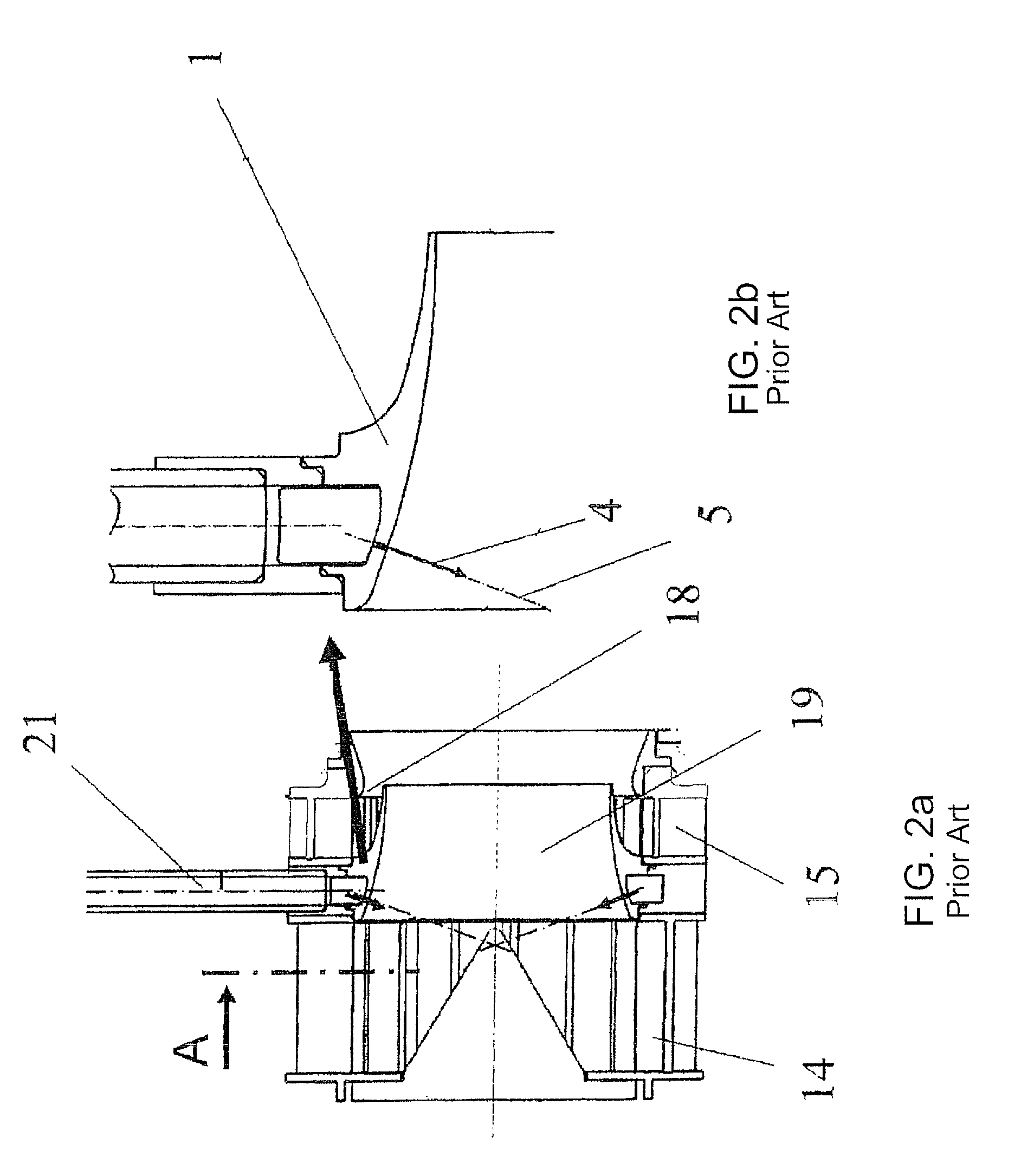
For purely constructional reasons, completely parallel fuel injection is not always possible.

Method used


Image

  • Fuel injection nozzle with film-type fuel application
  • Fuel injection nozzle with film-type fuel application
  • Fuel injection nozzle with film-type fuel application

Examples


Embodiment Construction

[0033]In the figures, like items are identified with like reference numerals.

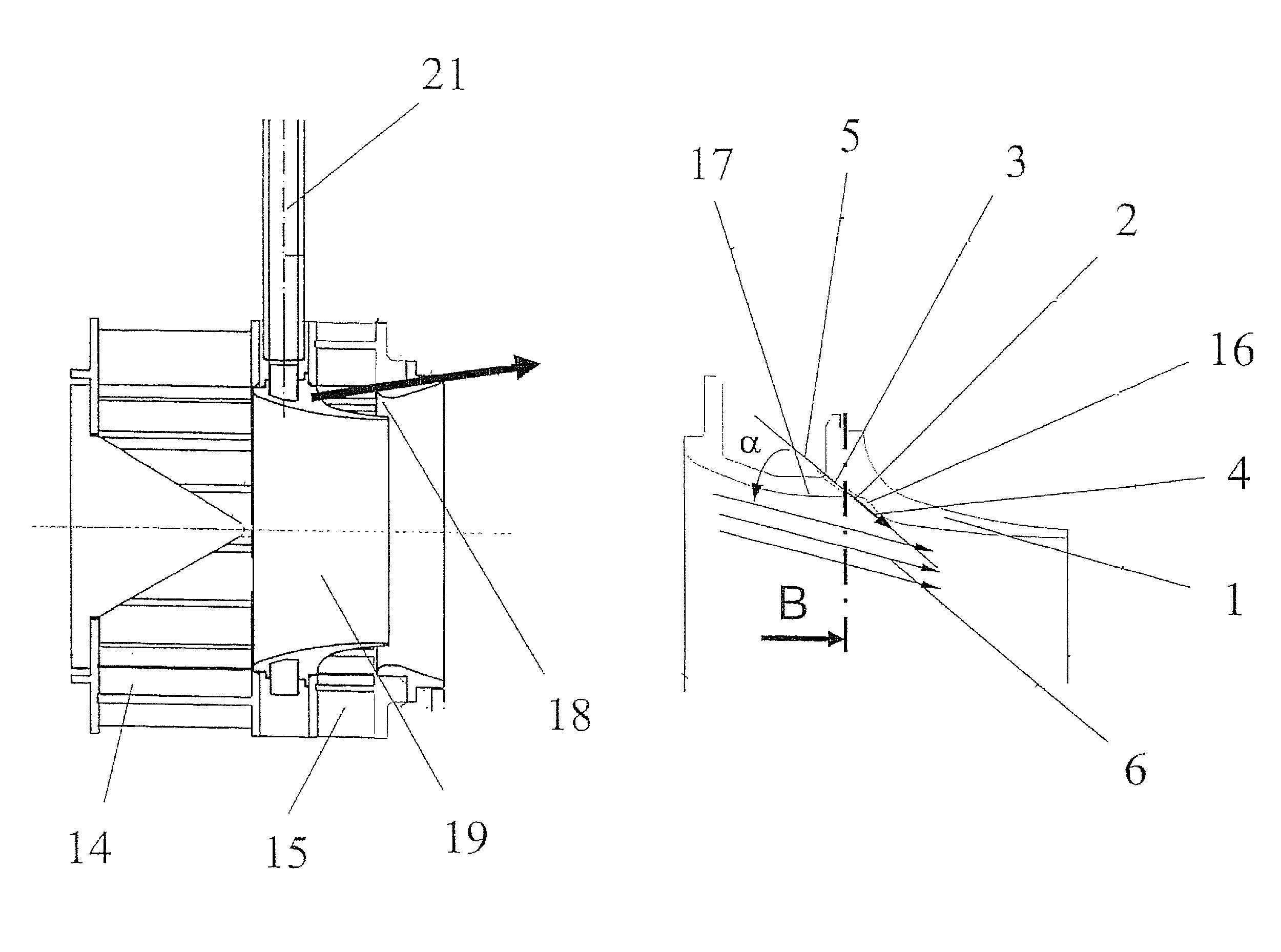
[0034]FIGS. 3a and 3b show, in simplified representation, a section through a film applicator 1 in accordance with the present invention, with fuel openings 2, in particular fuel holes 3, being illustrated whose center axes 5 are inclined at an angle α to the main flow direction 6 (near-wall flow direction in the inner swirl channel).

[0035]Reference numeral 16 indicates a yawing wall element of the film applicator 1, reference numeral 17 an aerodynamically conformal film applicator surface. Reference numeral 21 indicates a fuel line.

[0036]With the present invention, unintentional penetration of liquid fuel into areas with low flow velocities and the resultant non-uniform mixture of fuel and air are avoided. FIG. 3 shows a proposed embodiment. Here, the fuel is not injected radially inward, i.e. with a high radial component of the exit velocity of the fuel, into an inner swirl channel. Rather, a high axial c...


PUM


Abstract

A fuel injection nozzle for a gas turbine combustion chamber with a film applicator (1) is provided with several fuel openings (2). Center axes (5) of the fuel openings (2) through the film applicator (1), with regard to their radial orientation, are essentially parallel to the main flow direction (6) of the air.

Description

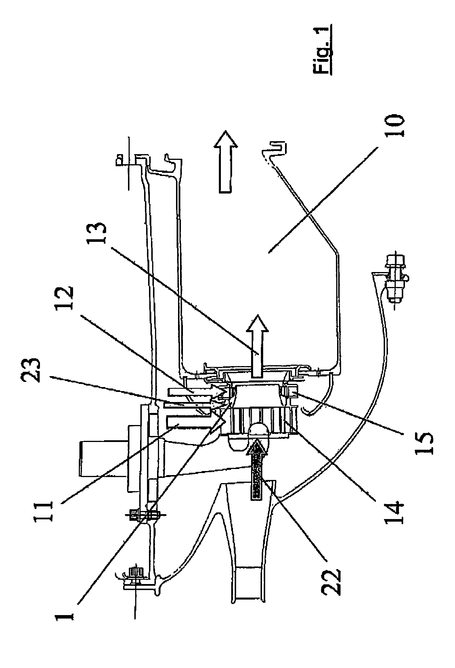
[0001]This application claims priority to German Patent Application DE10348604.6 filed Oct. 20, 2003, the entirety of which is incorporated by reference herein.BACKGROUND OF THE INVENTION[0002]This invention relates to a fuel injection nozzle. More particularly, this invention relates to a fuel injection nozzle for a gas turbine combustion chamber with a film applicator provided with several fuel openings.[0003]A great variety of methods is used to prepare the fuel-air mixture in gas turbine combustion chambers, with distinction being basically made between their application to stationary gas turbines or aircraft gas turbines and the respective specific requirements. However, in order to reduce pollutant emissions, in particular nitrogen oxide emissions, the fuel must generally be premixed with as much air as possible to obtain a lean combustion state, i.e. one characterized by air excess. Such a mixture is, however, problematic since it may affect stabilizing mechanisms in the comb...

Claims


Application Information

Patent Timeline
Patent Type & Authority Patents(United States)
IPC IPC(8): B05B7/10F23D11/10F23R3/28
CPCF23D11/106F23D11/107F23R3/28F23D2900/11101
Inventor RACKWITZ, LEIF
Owner ROLLS ROYCE DEUT LTD & CO KG
Learn More