
Image reconstruction in computed tomography

a computed tomography and image reconstruction technology, applied in image data processing, diagnostics, applications, etc., can solve the problems of limited measurement data, limited resolution of ct images, image corruption, etc., and achieve the effect of optimizing the shrinkage function of image domains and minimizing differences

Inactive Publication Date: 2015-05-19
TECHNION RES & DEV FOUND LTD
View PDF2 Cites 11 Cited by
  • Summary
  • Abstract
  • Description
  • Claims
  • Application Information

AI Technical Summary

Benefits of technology

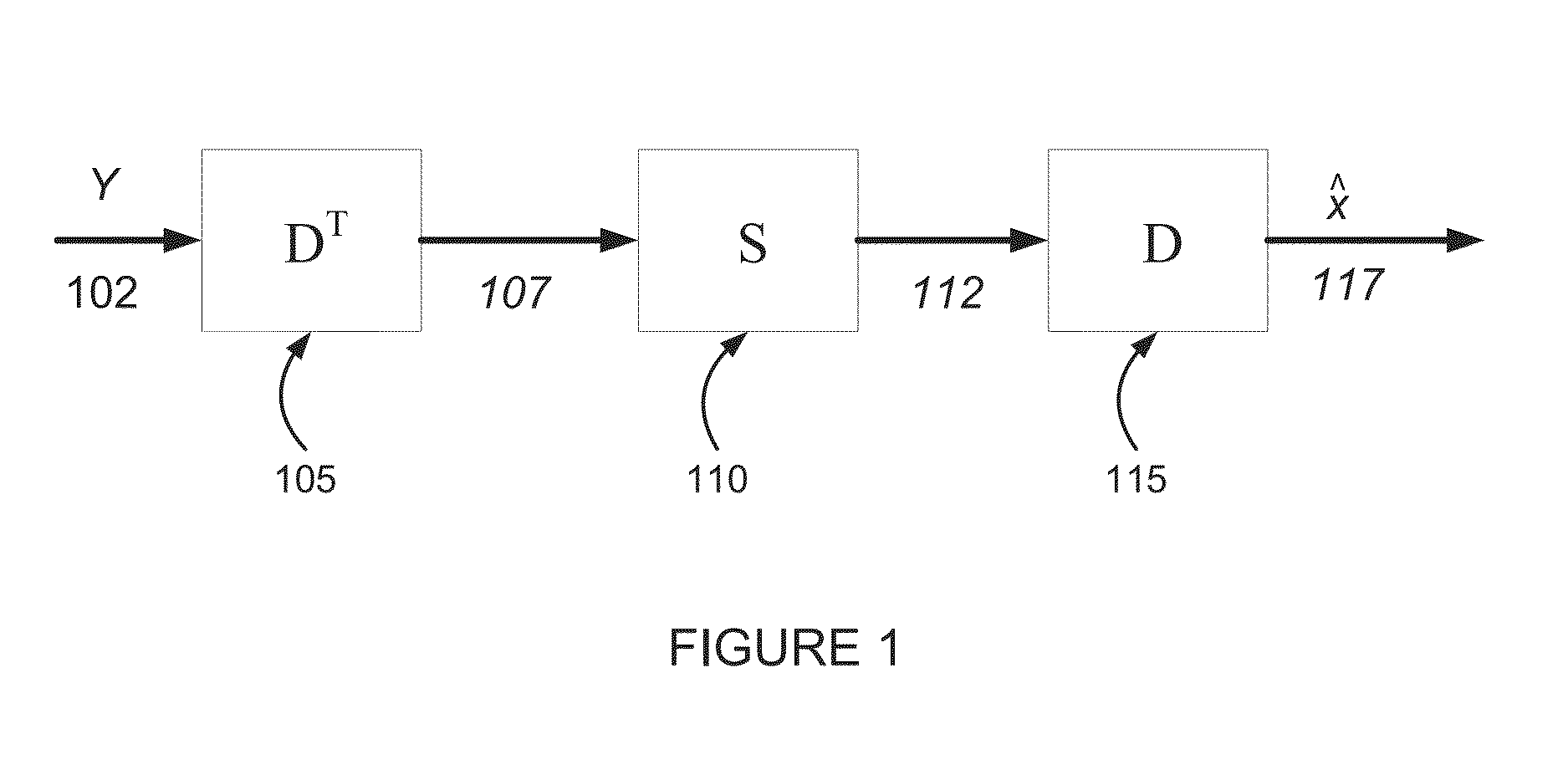
The patent describes methods for reconstructing digital images from projections using a local transform and a shrinkage function. The methods involve applying a sparsifying transform and a shrinkage function to the projection data, followed by an inverse of the sparsifying transform, to produce a restored image. The restored image is then filtered using a second, image domain, shrinkage function to produce a filtered restored image. The filtered restored image is compared to the target image, and an optimized image domain shrinkage function is produced to minimize the differences between the filtered restored image and the target image. The technical effects of the methods include improved image quality and reduced computation time.

Problems solved by technology

In practice, measurement data is limited by a discrete sampling scheme, and is degraded by a number of physical phenomena occurring in a scanner.
The first mentioned problem is an inevitable but minor cause for the limited resolution in the CT images; mainly, the images are corrupted by the data degradation factors.
Another source of deterioration, which is dominant in a low-dose scenario, is stochastic noise.
One type of noise stems from low photon counts, which occur when the X-rays pass through high-attenuation areas.
Another type of noise originates from the noise present in the detectors.
As a result, the problem of photon starvation manifests in the output image in the form of streak artifacts.
Each measured line integral is effectively smeared back over that line through the image by the back-projection; an incorrect measurement results in a line of wrong intensity in the image.
Typically, the streaks radiate from bone regions or metal implants, which corrupt its contents and jeopardize its diagnostic value.
A drawback of reconstruction based on explicit statistical modeling is a computationally heavy iterative solution.
The techniques are applied in a non-iterative fashion, and have a computational complexity comparable to the FBP.

Method used


Image

  • Image reconstruction in computed tomography
  • Image reconstruction in computed tomography
  • Image reconstruction in computed tomography

Examples


Embodiment Construction

[0100]The present invention, in some embodiments thereof, relates to computed tomography, and, more particularly, but not exclusively, to methods for reconstruction of images from projected data in computed tomography.

[0101]In reconstructing computed tomography images according to some embodiments of the invention, the raw data, or sinogram, is in what may be called the transform domain. CT Images are produced from the raw data by applying a learned shrinkage function, and transforming into the image domain.

[0102]It is noted that CT images are typically three-dimensional, volumetric images. Example images described herein include two-dimensional images. However, persons skilled in the art will easily recognize when what is described in terms of a two-dimensional image is also applicable to three-dimensional, volumetric, images.

[0103]The term “image” in all its grammatical forms is used throughout the present specification and claims where applicable, to stand for both a two-dimensio...


PUM


Abstract

A method of projection domain processing based on a local transform and shrinkage for use in reconstructing digital images from a set of projections, the method including providing a target image of a target object, providing projection data of the target object, producing filtered projection data by applying a sparsifying transform and a shrinkage function to the projection data, followed by an inverse of the sparsifying transform, producing a restored image by applying a reconstruction transform to the filtered projection data, comparing the restored image to the target image, and producing an optimized projection domain shrinkage function by adapting the shrinkage function to minimize differences between the restored image and the target image. Related apparatus and methods are also described.

Description

RELATED APPLICATION[0001]This application claims the benefit of priority under 35 USC §119(e) of U.S. Provisional Patent Application No. 61 / 719,451 filed Oct. 28, 2012, the contents of which are incorporated herein by reference in their entirety.FIELD AND BACKGROUND OF THE INVENTION[0002]The present invention, in some embodiments thereof, relates to Computed Tomography (CT), and, more particularly, but not exclusively, to methods for reconstruction of images from projection data in computed tomography.[0003]A Computed Tomography (CT) scan enables estimation of attenuation coefficients of scanned object components by comparing a flow of photons entering and exiting the scanned object along straight lines. Theoretically, a log-transformed photon count information corresponds to an X-ray transform of the attenuation function, and should provide a perfect reconstruction. In practice, measurement data is limited by a discrete sampling scheme, and is degraded by a number of physical pheno...

Claims


Application Information

Patent Timeline
Patent Type & Authority Patents(United States)
IPC IPC(8): G06K9/00G06T11/00A61B6/00
CPCG06T11/006G06T2211/424
Inventor ELAD, MICHAELSHTOK, JOSEPHZIBULEVSKY, MICHAEL
Owner TECHNION RES & DEV FOUND LTD
Learn More