Laser coagulation of an eye structure or a body surface from a remote location

a laser coagulation and eye technology, applied in the field of laser coagulation of the eye or the body surface, can solve the problems of severe vision loss, contact lens use for laser application, and corneal refractive power loss that is not suitable for conventional slit lamp systems

Active Publication Date: 2015-05-19
PEYMAN GHOLAM A
View PDF32 Cites 16 Cited by
  • Summary
  • Abstract
  • Description
  • Claims
  • Application Information

AI Technical Summary

Benefits of technology

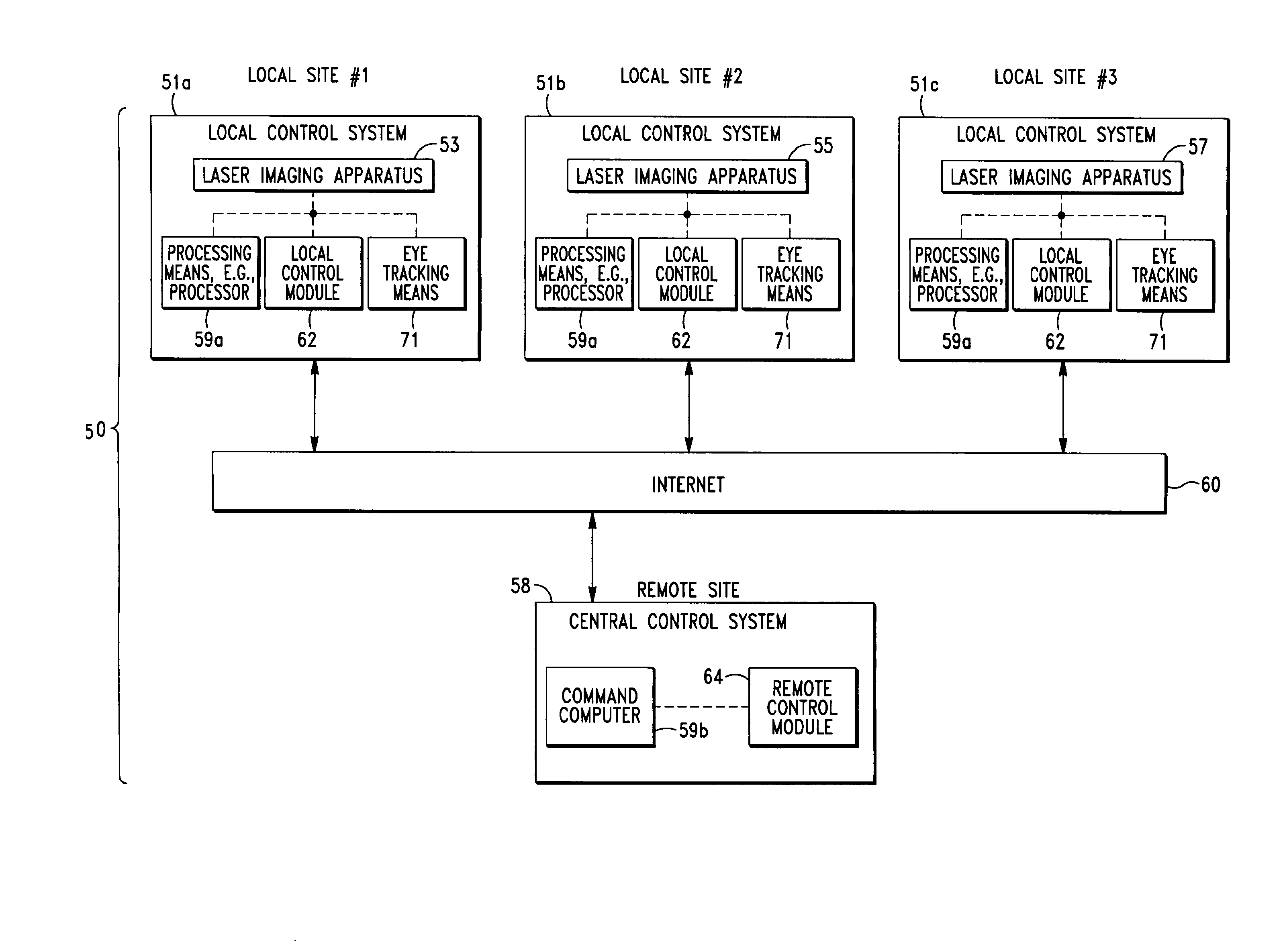
[0024]The present invention is directed to laser imaging and coagulation apparatus, systems and methods that allow an eye specialist, e.g., an ophthalmologist or surgeon, to perform laser surgery on an eye structure, e.g. retina, with an integral laser imaging and coagulation apparatus disposed at a first (i.e. local) location from a control system disposed at a second (i.e. remote) loc

Problems solved by technology

Indeed, if not treated at the appropriate stage, noted diseases, particularly, diabetic retinopathy, can lead to severe losses in vision.
A major drawback associated with each of the noted conventional systems, as well as most known laser coagulation systems (and associated methods), is that the conventional slit lamp systems require a contact lens to neutralize the refractive power of the cornea.
There are several drawbacks associated with the use of a contact lens during laser coagulation.
A major drawback is that the use of a contact lens requires topical anesthesia and a dilated pupil for laser application.
As is well known in the art, a contact lens can, and in many instances will, cause corneal abrasion on an anesthetized cornea.
A further drawback associated with conventional laser coagulation procedures is that the laser procedures are dependent on the steadiness of the physician's hands and the subject's head.
Although laser delivery with an indirect ophthalmos

Method used


Image

  • Laser coagulation of an eye structure or a body surface from a remote location
  • Laser coagulation of an eye structure or a body surface from a remote location
  • Laser coagulation of an eye structure or a body surface from a remote location

Examples


Embodiment Construction

[0089]Before describing the present invention in detail, it is to be understood that this invention is not limited to particularly exemplified apparatus, systems, structures or methods as such may, of course, vary. Thus, although a number of apparatus, systems and methods similar or equivalent to those described herein can be used in the practice of the present invention, the preferred apparatus, systems, structures and methods are described herein.

[0090]It is also to be understood that the terminology used herein is for the purpose of describing particular embodiments of the invention only and is not intended to be limiting.

[0091]Unless defined otherwise, all technical and scientific terms used herein have the same meaning as commonly understood by one having ordinary skill in the art to which the invention pertains.

[0092]Further, all publications, patents and patent applications cited herein, whether supra or infra, are hereby incorporated by reference in their entirety.

[0093]Fina...


PUM


Abstract

An integral laser imaging and coagulation apparatus, and associated systems and methods that allow a physician (e.g., a surgeon) to perform laser surgical procedures on an eye structure or a body surface with an integral laser imaging and coagulation apparatus disposed at a first (i.e. local) location from a control system disposed at a second (i.e. remote) location, e.g., a physician's office. In some embodiments, communication between the integral laser imaging and coagulation apparatus and control system is achieved via the Internet®.

Description

CROSS-REFERENCE TO RELATED APPLICATIONS[0001]This is a continuation-in-part of U.S. patent application Ser. No. 13 / 573,100, filed Aug. 20, 2012, which is a continuation-in-part of U.S. patent application Ser. No. 12 / 925,518, filed Oct. 22, 2010, which claims the benefit of U.S. Provisional Application No. 61 / 455,111, filed Oct. 13, 2010; the disclosure of each of which is hereby incorporated by reference as if set forth in their entirety herein.FIELD OF THE INVENTION[0002]The present invention relates to methods and systems for laser coagulation of the eye or a body surface. More particularly, the present invention relates to non-invasive and non-contact methods and systems for laser coagulation of predetermined portions of the biological organism in the eye; particularly, the retina, or an external body surfaceBACKGROUND OF THE INVENTION[0003]As is well known in the art, various eye disorders, such as diabetic retinopathy, vascular occlusion, neovascularization and age macular dege...

Claims


Application Information

Patent Timeline
IPC IPC(8): A61B5/05A61B18/20A61B19/00A61F9/008
CPCA61B18/20A61B19/50A61F9/00821A61F9/00804A61F9/00825A61F2009/00846A61F2009/00863A61B5/0095
Inventor PEYMAN, GHOLAM A.
Owner PEYMAN GHOLAM A
Why Eureka
Try Eureka