Aerated contact lens assembly

a contact lens and assembly technology, applied in the direction of spectacles/goggles, instruments, spectacles/goggles, etc., can solve the problems of limited oxygen exchange capacity, lens unsuitable for extended wear, and insufficient oxygen permeability of presently available rgp plastic,

Active Publication Date: 2015-05-26
RGT UNIV OF CALIFORNIA
View PDF9 Cites 35 Cited by
  • Summary
  • Abstract
  • Description
  • Claims
  • Application Information

AI Technical Summary

Benefits of technology

[0007]The present invention comprises a composite contact lens that provides access to atmospheric oxygen to the cornea, even when the front part of the lens, including major optical elements, is made of a gas-impermeable material. The invention provides for the construction of thick optical arrangements, which may be worn as contact lenses while providing the cornea with sufficient access to the atmospheric oxygen (aeration) and enabling the transport of carbon dioxide from the cornea to the atmosphere.
[0009]The air-filled cavity has the oxygen permeability of air (a gas mixture of nitrogen, oxygen, and other components), which is the same as the diffusion coefficient of oxygen in air: ˜0.2 cm2 / s×[mL O2 / mL material×atm], which is more than five orders of magnitude higher than the oxygen permeability of the most permeable RGP plastics. The placement of an air-filled cavity directly above the thin gas-permeable layer effectively provides direct access to oxygen through the thin layer without impairment by the optical element(s).

Problems solved by technology

The optimal thickness of such assemblies may exceed the ˜1 mm limit beyond which the oxygen permeability of presently-available RGP plastic becomes insufficient.
Furthermore, construction of such assemblies may necessitate the use of oxygen-impermeable materials, which would block the transport of oxygen from the atmosphere to the cornea, making the lens unsuitable for extended wear.
Both the capsule and the electro-active lens would interfere with oxygen transport, such that the oxygen exchange capability would be limited and not appreciably improved relative to a monolithic contact lens with the same external dimensions.
As a result, inclusion of a fluid or gel within a cavity will necessarily impair the transport of oxygen through the cavity from atmosphere to the cornea.

Method used


Image

  • Aerated contact lens assembly
  • Aerated contact lens assembly
  • Aerated contact lens assembly

Examples


Embodiment Construction

[0023]For purposes of the following description, certain terms may be used interchangeably while referring to the same object. In particular, the word “gas” includes, but is not limited to, oxygen and carbon dioxide. The terms “communication”, “diffusion” and “transport” may be used interchangeably to refer to the movement of gas within and / or across lens components.

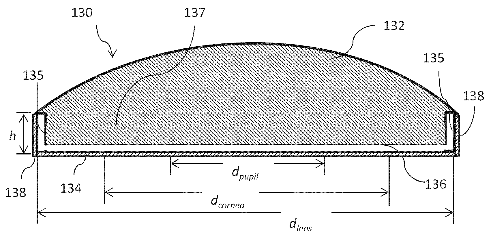
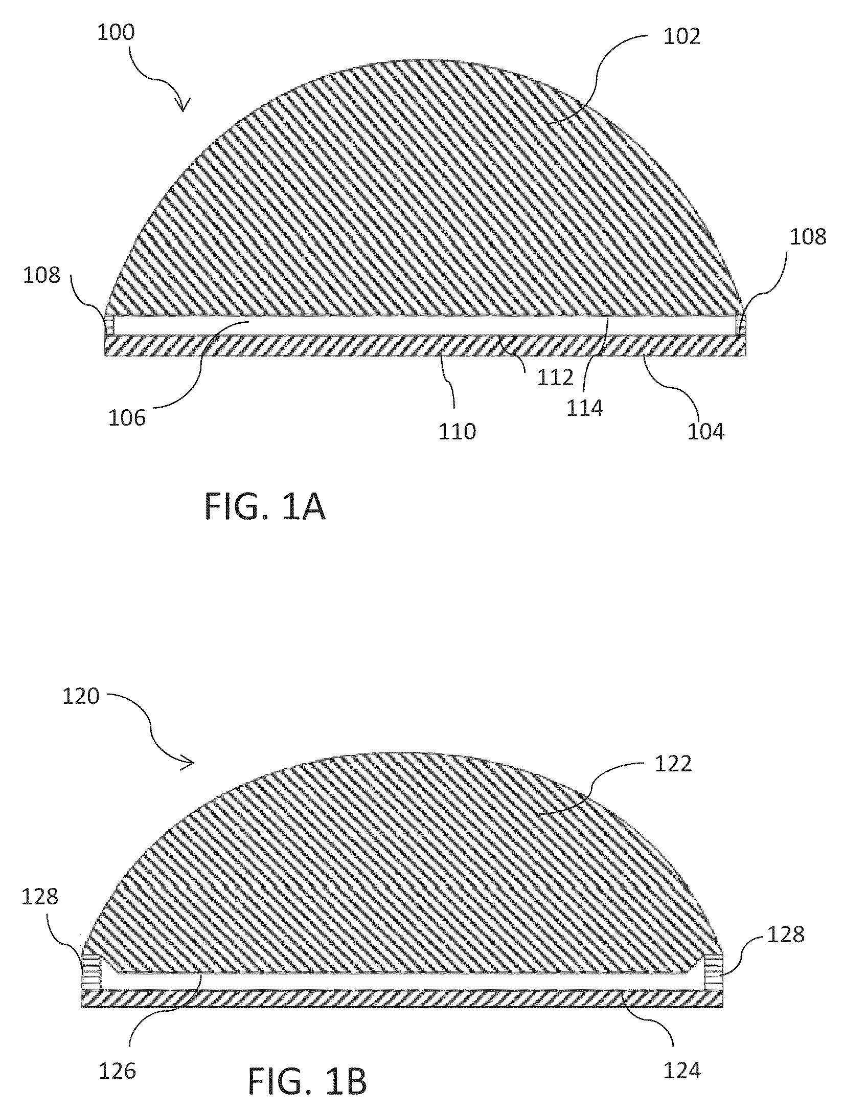
[0024]FIG. 1A provides a schematic drawing of the cross-section of an embodiment of the invention. The composite lens 100 has axial symmetry with three layers: layer 104, a thin oxygen permeable layer adjacent to the surface of the eye, which can be made of an RGP plastic, layer 102, a thick transparent optical assembly, which may be oxygen impermeable, and layer 106, an air-filled cavity. Surface 110 corresponds to the surface of the lens that is immediately adjacent to the eye surface and, although illustrated as a flat surface, will be made with curvature appropriate for the wearer's eye. Surface 110 may be in physica...


PUM


Abstract

A contact lens assembly includes a proximal layer formed from a gas-permeable material, a distal layer with an optical element, an air cavity disposed between the proximal layer and the distal layer, wherein oxygen concentration across the air cavity is substantially uniform, and an gas transport region surrounding the air cavity for communicating gas between the air cavity and atmosphere. The contact lens assembly may further include a plurality of fins disposed within the air cavity where the plurality of fins has openings therethrough. One or both of the upper and lower surfaces of the air cavity may have an anti-reflection coating formed thereon.

Description

RELATED APPLICATIONS[0001]The present application claims the benefit of priority of U.S. Provisional Application No. 61 / 637,624, filed Apr. 24, 2012, which is incorporated herein by reference in its entirety.BACKGROUND OF THE INVENTION[0002]Most contact lenses on the market today are made of rigid gas permeable (RGP) plastics, hydrogels, or composite silicone-hydrogel materials. An essential requirement to contact lenses is oxygen permeability, so that the cornea of the eye, which lacks vascularization, has access to atmospheric oxygen and remains healthy when the lens is worn over a prolonged period of time. Materials have been developed that are optically transparent, durable, and have high oxygen permeability. A common requirement for a contact lens is that its oxygen permeability, Dk, must be higher than 10-20×10−9 cm / s×[mL O2 / mL material×mmHg]. The highest oxygen permeability of the currently-used RGP plastics is ˜150×10−11 cm2 / s×[mL O2 / mL material×mmHg] (examples include MENIC...

Claims


Application Information

Patent Timeline
Patent Type & Authority Patents(United States)
IPC IPC(8): G02C7/04
CPCG02C7/04G02C7/047G02C7/049G02C2202/16
Inventor GROISMAN, ALEXANDER
Owner RGT UNIV OF CALIFORNIA
Why Eureka
Try Eureka