Method and system for engine control

a technology of engine control and engine start, applied in the direction of electric control, engine starters, instruments, etc., can solve the problem that the operator may expect a longer starting time, and achieve the effect of reducing vehicle noise, fuel saving, and reducing exhaust emissions

Inactive Publication Date: 2015-05-26
FORD GLOBAL TECH LLC
View PDF7 Cites 7 Cited by
  • Summary
  • Abstract
  • Description
  • Claims
  • Application Information

AI Technical Summary

Benefits of technology

[0002]Vehicles have been developed to perform an engine stop when idle-stop conditions are met and then to automatically restart the engine when restart conditions are met. Such idle-stop systems enable fuel savings, reduced exhaust emissions, reduced vehicle noise, and the like.
[0003]Other engines may be configured with variable cam timing mechanisms wherein cam timing can be adjusted at engine shut-down to reduce engine emissions and the potential for engine misfire. By repositioning the cam in response to a request to stop the engine, pumping of air to the exhaust system can be reduced so that engine emissions can be improved. Cam timing may also be adjusted during engine restarting to reduce engine speed flare.
[0004]However, the inventors herein have recognized that there may be conflicting requirements when the engine is automatically shut-down by an engine controller of the idle-stop system (e.g., in response to selected idle-stop conditions being met and without an operator request to stop the engine) versus when the engine is shutdown by the operator. For example, if an engine is stopped via a controller to save fuel during an engine idle period, it may be reasonably expected that the engine will be restarted within a short time period to provide torque to propel the vehicle since the driver has not requested that the engine be stopped. Restarting the engine when the engine is warm and has relatively low friction as compared to when the engine is cold may require less engine torque. As such, a reduced cylinder air charge may be necessary to restart the engine. Further, by reducing the amount of air supplied to engine cylinders during a warm engine restart, it may be possible to reduce engine emission and engine speed overshoot to improve engine starting. In addition, a short engine start time driven by an operator torque request and facilitated by determining engine position at stop may be expected by the operator. Thus, it may be desirable to position the intake valve cam in a retarded position during engine shutdown (e.g., the time between an engine stop request and zero engine rotation) so that the engine may be restarted during warm conditions with a reduced air charge.
[0007]By adjusting intake valve closing timing to timings that depend on whether the engine stop request was generated via an engine controller or an operator, it may be possible to pre-position intake valve closing timing such that the engine is better prepared for a subsequent engine restart. For example, if the engine is stopped automatically via a controller during warm ambient conditions, cam timing can be retarded in anticipation that a smaller cylinder air charge may be used to restart the engine and limit engine speed overshoot. Further, retarded valve timing may reduce engine shake during engine stopping. Conversely, if the engine is stopped via an operator request, cam timing can be set to a more advanced position so that the engine cylinders receive additional air during a subsequent engine restart. In this way, the engine may be restarted with increased torque during cold conditions to positively accelerate the engine.
[0010]In this way, by adjusting the valve timing differently based on the differences between an engine idle-stop and an engine operator shutdown request, as well as the various engine adjustments performed during an engine idle-stop, the engine may be kept engine restart ready.

Problems solved by technology

However, the inventors herein have recognized that there may be conflicting requirements when the engine is automatically shut-down by an engine controller of the idle-stop system (e.g., in response to selected idle-stop conditions being met and without an operator request to stop the engine) versus when the engine is shutdown by the operator.
Further, since the engine may be cold the operator may expect a longer starting time.

Method used


Image

  • Method and system for engine control
  • Method and system for engine control
  • Method and system for engine control

Examples


Embodiment Construction

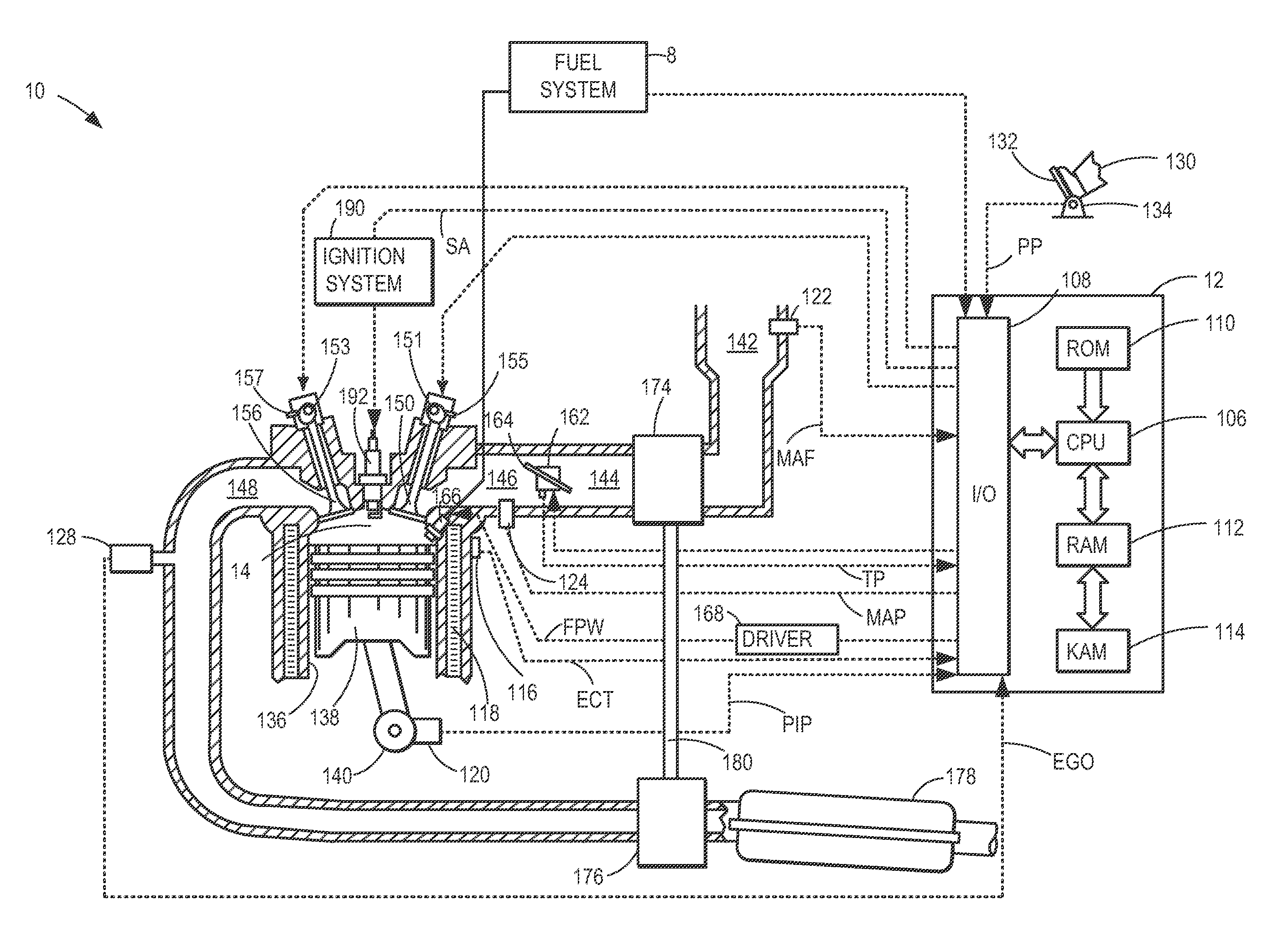
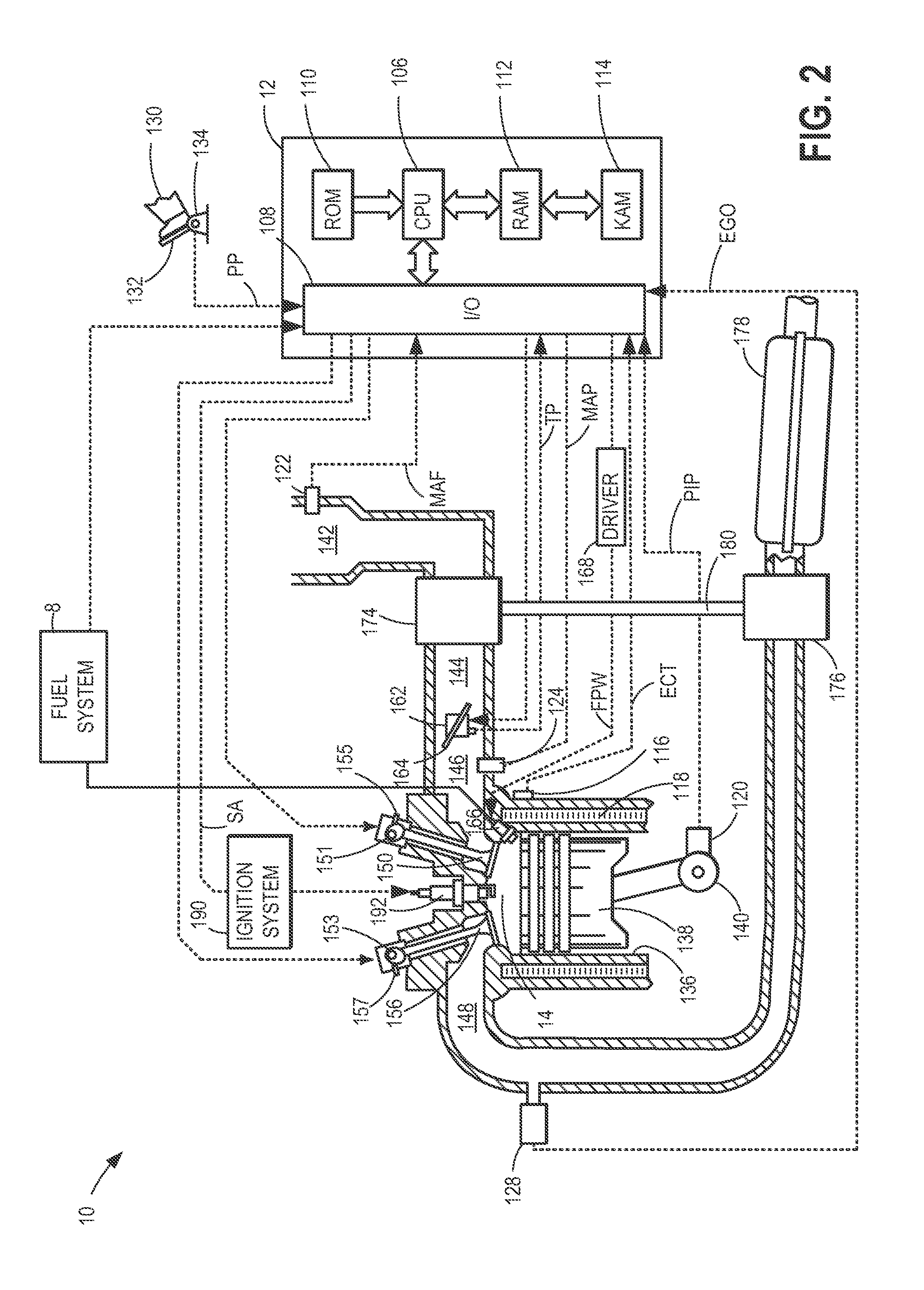
[0017]The following description relates to systems and methods for engine systems configured to be automatically deactivated in response to selected idle-stop conditions, such as the engine system of FIGS. 1-2. Specifically, engine stopping and start may be improved by reducing shutdown shake experienced during an engine shutdown, and reducing engine speed flare during a subsequent engine restart. An engine controller may be configured to perform control routines, such as those depicted in FIGS. 3-4, during an engine idle-stop and / or restart operation, to adjust a cylinder valve timing for improved compression heating and to provide an anticipated cylinder air charge, based on whether an engine shutdown is deliberately performed, in response to an operator request, or automatically performed, in response to idle-stop conditions. Specifically, a cam timing device may be operated to preposition the valve timing during an engine shutdown based the origin of the engine stop request. In ...


PUM


Abstract

Methods and systems are provided for controlling an engine system with a variable cam timing device. In one example, the variable cam timing device is operated to adjust engine valve timing differently at engine stop based on whether the engine stop is in response to an operator request or in response to an automatic controller initiated engine stop without an operator request.

Description

FIELD[0001]The present application relates to methods and systems for controlling an engine shut-down and / or a subsequent engine restart.BACKGROUND AND SUMMARY[0002]Vehicles have been developed to perform an engine stop when idle-stop conditions are met and then to automatically restart the engine when restart conditions are met. Such idle-stop systems enable fuel savings, reduced exhaust emissions, reduced vehicle noise, and the like.[0003]Other engines may be configured with variable cam timing mechanisms wherein cam timing can be adjusted at engine shut-down to reduce engine emissions and the potential for engine misfire. By repositioning the cam in response to a request to stop the engine, pumping of air to the exhaust system can be reduced so that engine emissions can be improved. Cam timing may also be adjusted during engine restarting to reduce engine speed flare.[0004]However, the inventors herein have recognized that there may be conflicting requirements when the engine is ...

Claims


Application Information

Patent Timeline
Patent Type & Authority Patents(United States)
IPC IPC(8): B60W10/04B60W30/18F02D41/00F02D41/02F02D41/04F02D41/06F02N11/00F02N11/08F02N15/00
CPCF02D41/0002F02D41/0215F02D41/042F02D41/064F02D41/065F02D41/0025Y10T477/675B60W10/04B60W30/18F02D41/022F01L2800/03F02D2041/001F02D2200/0414F02D2200/703Y02T10/42F02N11/00F02N11/0814F02N11/0822F02N11/0844F02N15/006Y02T10/40F02D9/00F02D13/0215
Inventor DOERING, JEFFREY ALLENULREY, JOSEPH NORMANGIBSON, ALEX O'CONNOR
Owner FORD GLOBAL TECH LLC
Why Eureka
Try Eureka