Control method of robot apparatus and robot apparatus

a robot and robot technology, applied in the direction of programmed manipulators, programme control, instruments, etc., can solve the problems of reducing the operating time of the robot, the minimum control input of the robot, and the difficulty of controlling the controllability of the artificial muscle actuator, so as to extend the operating time and optimize the stiffness of the joint

Inactive Publication Date: 2015-06-02
CANON KK
View PDF21 Cites 5 Cited by
  • Summary
  • Abstract
  • Description
  • Claims
  • Application Information

AI Technical Summary

Benefits of technology

[0010]According to the present invention, the iterative computation algorithm for simultaneously optimizing the stiffness of the joint and the trajectory of the joint can generate feedforward input for antagonistically driving the actuators based on minimum driving force command values relative to the target trajectory. The minimization of the driving force command values can minimize, for example, an amount of consumed air in the McKibben artificial muscles. This can extend the operating time in a robot apparatus that uses an on-board air supply such as a tank.

Problems solved by technology

However, the artificial muscle actuators are known to have difficulties in controllability for reasons that the viscoelasticity characteristics indicate non-linearity and that the actuators need to be antagonistically arranged and controlled because the force is generated only in a contraction direction.
However, there is no study example for antagonistically driving the artificial muscle actuators by minimum control input.

Method used


Image

  • Control method of robot apparatus and robot apparatus
  • Control method of robot apparatus and robot apparatus
  • Control method of robot apparatus and robot apparatus

Examples


first embodiment

[0039

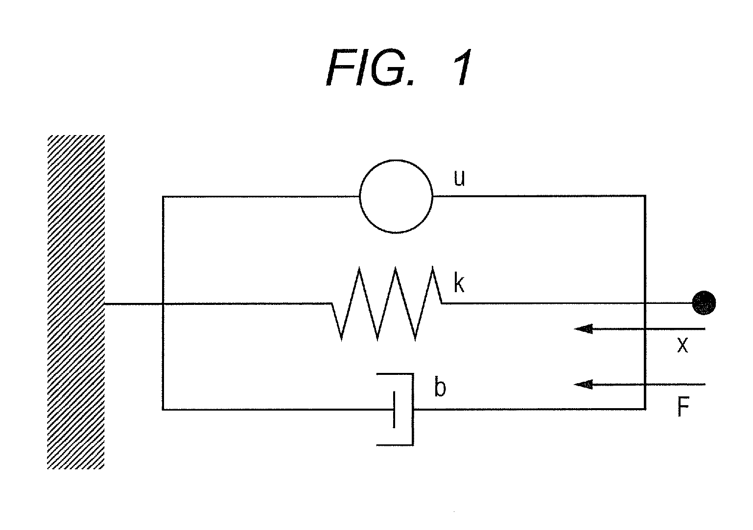
[0040]FIG. 1 is a diagram illustrating a viscoelasticity model of an actuator applied to a robot apparatus according to a first embodiment of the present invention. The present first embodiment describes an example of simultaneous control of a joint angle and stiffness of a joint of a manipulator using pneumatic artificial muscle actuators in a robot apparatus.

[0041](1) Modeling

[0042]The artificial muscle actuator is an actuator with characteristics similar to characteristics called viscoelasticity of muscle. As illustrated in FIG. 1, the artificial muscle actuator is modeled using a force generation element, an elasticity element and a viscosity element. Contractile force of the force generation element is defined as u, and an amount of contraction of muscle is defined as x wherein a contraction direction is positive. The following formula denotes a contractile rate.

{dot over (x)}

[0043]An elastic force constant is defined as k, a viscous force constant is defined as b, and mus...

second embodiment

[0081

[0082]A robot apparatus according to a second embodiment of the present invention will be described. In the present second embodiment, control operation by a control unit is different from the control operation by the control unit of the first embodiment. In the configuration of the main body of the robot apparatus, components with similar configurations as those of the main body of the robot apparatus of FIG. 1 described in the first embodiment are designated with the same reference numerals, and the detailed description is omitted.

[0083]The present second embodiment delivers a two-degree-of-freedom control system merging the feedforward control system illustrated in the first embodiment and a feedback control system. The feedback control system is delivered to allow simultaneously following the target trajectory and the joint stiffness command values obtained by the iterative computation algorithm. With only the feedforward control system, the control performance deteriorates...

third embodiment

[0104

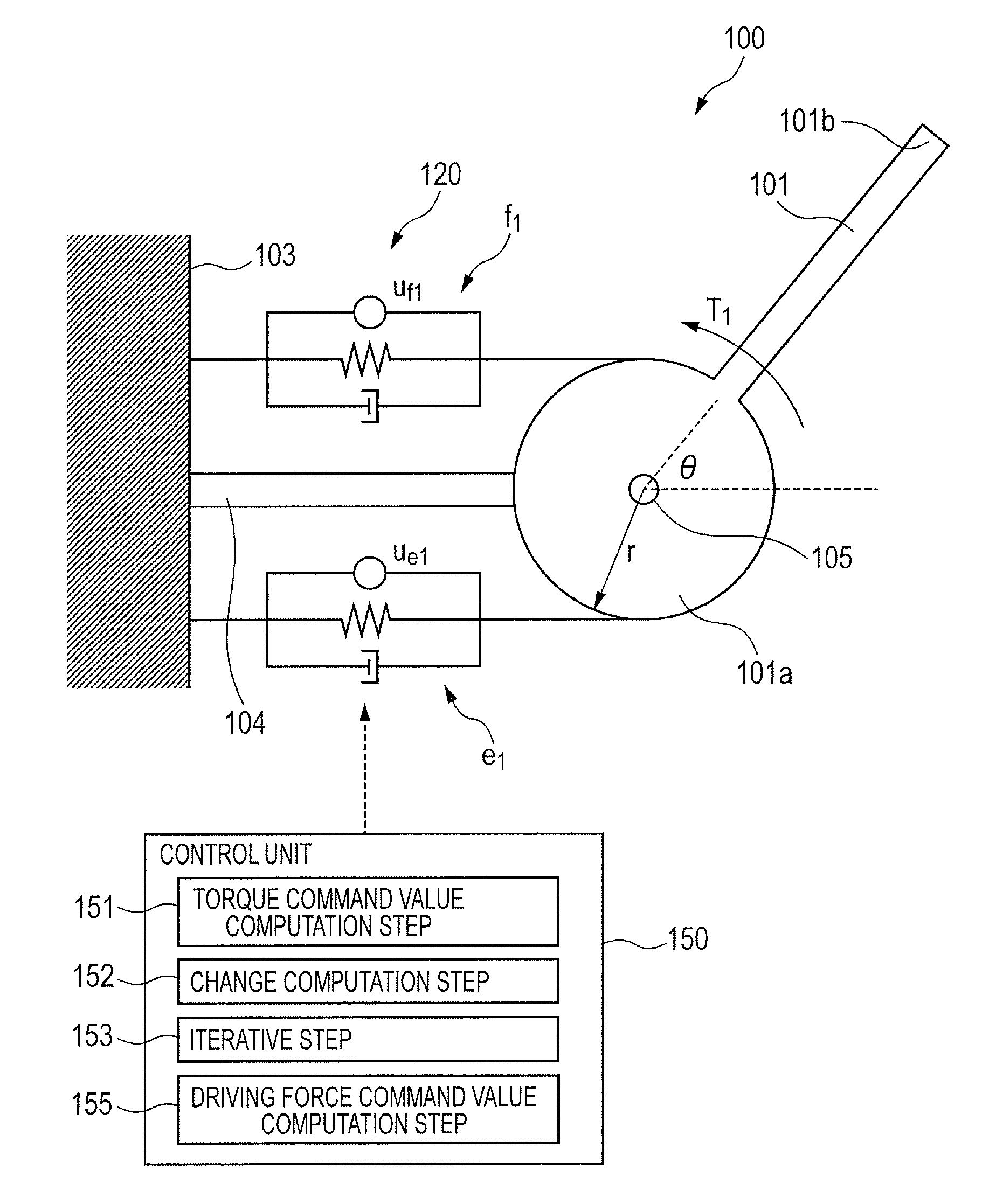
[0105]A robot apparatus according to a third embodiment of the present invention will be described in detail. FIG. 8 is an explanatory view illustrating a schematic configuration of the robot apparatus according to the third embodiment of the present invention. The present third embodiment describes an example of control of hand stiffness of a robot apparatus 200 as a two-link manipulator with three pairs (six muscles) of artificial muscle actuators.

[0106](1) Modeling

[0107]The robot apparatus 200 illustrated in FIG. 8 includes a pulley 203, a first link 201 pivotally connected to the pulley 203 through a first joint 211, and a second link 202 pivotally connected to the first link 201 through a second joint 212.

[0108]The first link 201 is made of a longitudinal member, and a base end 201a of the first link 201 is pivotally supported by the pulley 203 in a plane of an x-y rectangular coordinate system (hereinafter, called “work plane”). The second link 202 is made of a longitudin...


PUM


Abstract

A control method of a robot apparatus, the robot apparatus including a link and a pair of actuators, obtaining each driving force command value of each of the actuators, and controlling each of the actuators, the control method including: a torque command value computation step; a change computation step of computing a difference between the joint stiffness command value and a value and performing a computation of subtracting a value from the joint stiffness command value; an iterative step of iterating the computations of the torque command value computation step and the change computation step until the difference converges to a value equal to or smaller than a predetermined value; and a driving force command value computation step to compute each of the driving force command values when the difference is converged to a value equal to or smaller than the predetermined value.

Description

BACKGROUND OF THE INVENTION[0001]1. Field of the Invention[0002]The present invention relates to a control method of a robot apparatus including a hand that can flexibly touch an object and to the robot apparatus. The present invention can be applied to a working robot and a legged mobile robot.[0003]2. Description of the Related Art[0004]In a control method of a manipulator, it is becoming more important that a hand be able to flexibly touch an object. If the method is applied to an industrial robot, cooperative work of a robot apparatus and a human can be realized, and fitting work of components is facilitated by controlling the direction of the flexibility of the hand. If the method is applied to a legged mobile robot, impact on the body can be alleviated by soft landing, and absorption of a difference in level allows stable walking on an unleveled land.[0005]To realize the control of the flexibility of the hand, impedance control for installing a force sensor on the hand or cont...

Claims


Application Information

Patent Timeline
Patent Type & Authority Patents(United States)
IPC IPC(8): G05B15/00B25J9/16
CPCB25J9/1633G05B2219/39201G05B2219/41387
Inventor TAKAGI, KIYOSHI
Owner CANON KK
Why Eureka
Try Eureka