Electronic tag time-sharing control system and method thereof

a control system and electronic tag technology, applied in the field of electronic tag time-sharing control system, can solve the problems of low network bandwidth, inability to perform packet routing, and low overall performance, and achieve the effect of reducing the requirement for network bandwidth and prolonging the operating tim

Inactive Publication Date: 2012-12-27
CERAMICRO TECH
View PDF9 Cites 43 Cited by
  • Summary
  • Abstract
  • Description
  • Claims
  • Application Information

AI Technical Summary

Benefits of technology

[0011]In view of the aforementioned problems of the prior art, it is a primary objective of the present invention to provide an electronic tag time-sharing control system and a method thereof, capable of waking and updating display information of the plurality of wireless electronic tags and control the sleep mode in a time-sharing manner, so as to extend the operating time and lower the network bandwidth requirement.

Problems solved by technology

The end device can only select joining the formed ZigBee wireless network (PAN) and receive and transmit data, but cannot perform a routing of the packets.
1. If the quantity of end devices is huge, and all end device are standby simultaneously, the load of a coordinator and a router will be very heavy, and the bandwidth of a network will be insufficient for use, and the overall performance will be low. Packet collisions and use of some channels overlapped with WiFi, the problem of noise interference becomes increasingly greater as the quantity of end devices increases, and difficult to overcome.
2. Although the original design of ZigBee network architecture has taken the low power consumption into consideration, yet the end devices require a long idling time, and thus its power consumption is still high and the end devices fail to extend their ready-to work time.

Method used


Image

  • Electronic tag time-sharing control system and method thereof
  • Electronic tag time-sharing control system and method thereof
  • Electronic tag time-sharing control system and method thereof

Examples


Embodiment Construction

[0043]The technical content of the present invention will become apparent by the detailed description of the following embodiments and the illustration of related drawings as follows.

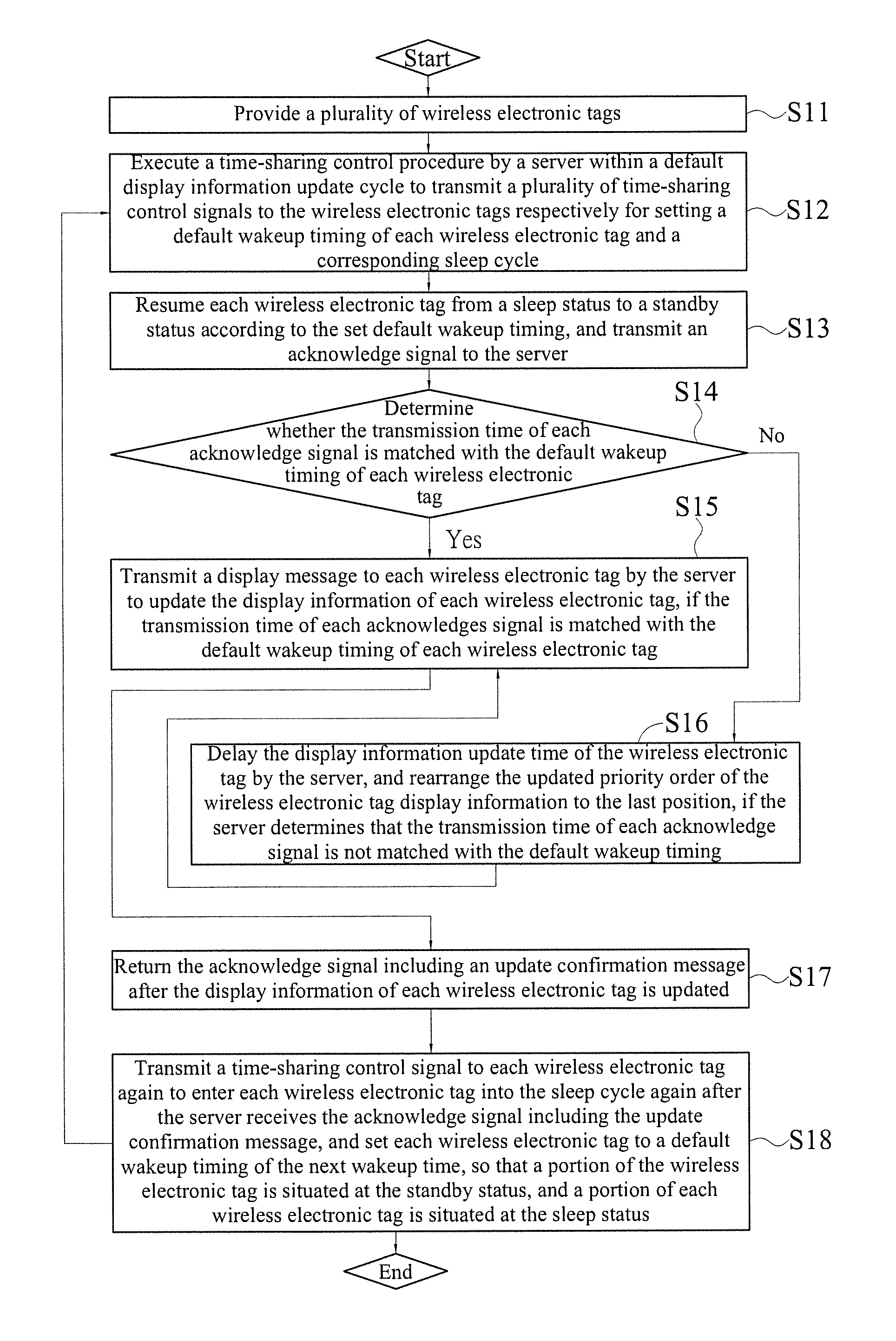
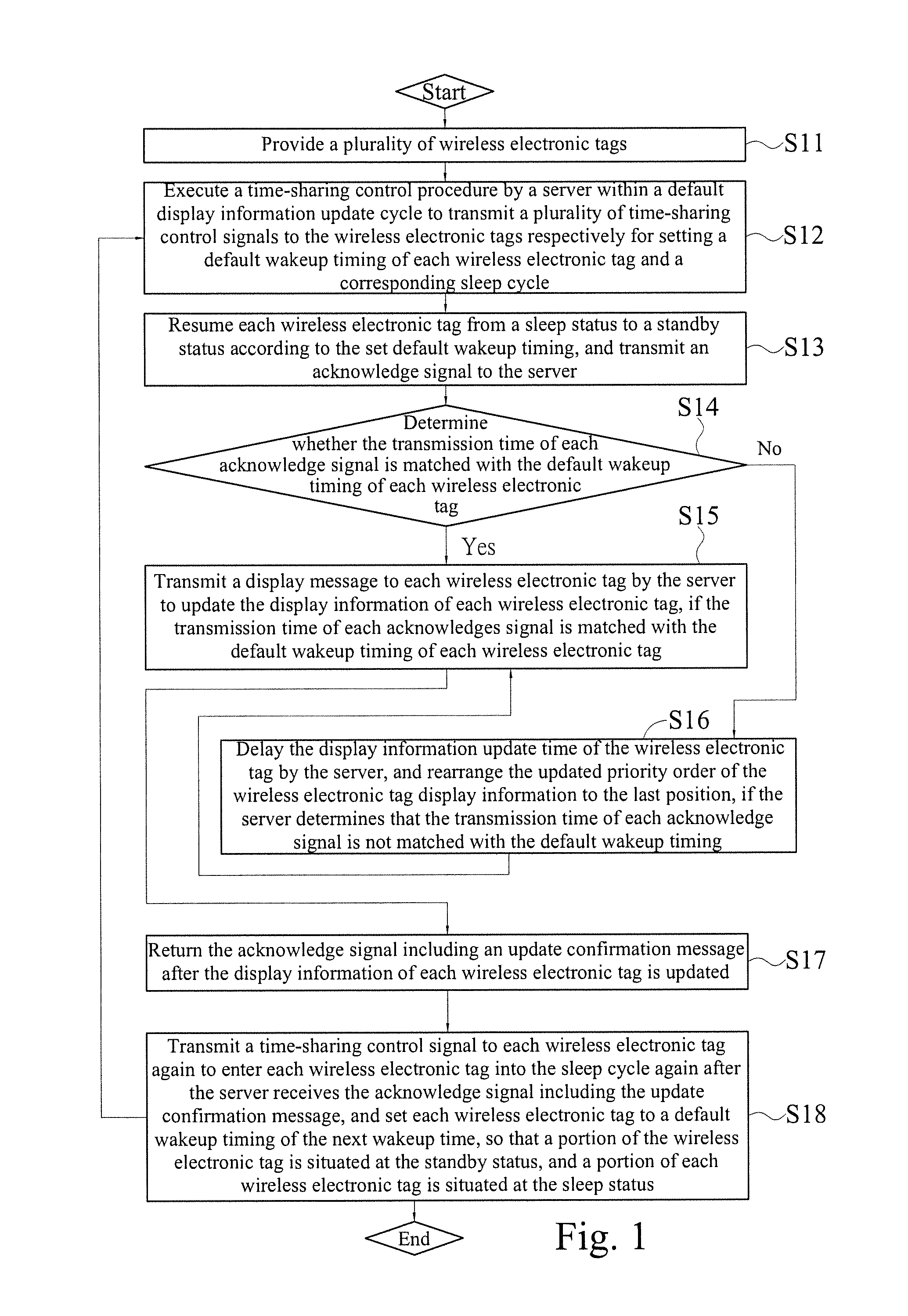
[0044]With reference to FIG. 1 for a flow chart of an electronic tag time-sharing control method in accordance with a preferred embodiment of the present invention, the electronic tag time-sharing control method comprises the following steps:

[0045]S11: Provide a plurality of wireless electronic tags.

[0046]S12: Execute a time-sharing control procedure by a server within a default display information update cycle to transmit a plurality of time-sharing control signals to the wireless electronic tags respectively for setting a default wakeup timing of each wireless electronic tag and a corresponding sleep cycle.

[0047]S13: Resume each wireless electronic tag from a sleep status to a standby status according to the set default wakeup timing, and transmit an acknowledge signal to the server respectively.

[0048...


PUM


Abstract

The present invention discloses an electronic tag time sharing control system and a method thereof, and the system comprises a server, at least one coordinator and a plurality of wireless electronic tags. The server transmits a time-sharing control signal. The coordinator and the server form a wireless connection for receiving and transmitting the time-sharing control signal. The wireless electronic tags and the coordinators form a wireless connection. After each wireless electronic tag receives the time-sharing control signal, different sleep cycle and wakeup timing are generated to update display information sequentially. A portion of the wireless electronic tag is situated at a sleep status and a portion of the wireless electronic tag is situated at a standby status to receive the update display information, so as to achieve the effects of saving bandwidth, reducing packet collisions and extending the service life of the wireless electronic tag.

Description

CROSS-REFERENCE TO RELATED APPLICATIONS[0001]This non-provisional application claims priority under 35 U.S.C. §119(a) on Patent Application No(s). 100211577 filed in Taiwan, R.O.C. on Jun. 24, 2011, the entire contents of which are hereby incorporated by reference.BACKGROUND OF THE INVENTION[0002]1. Field of the Invention[0003]The present invention relates to a time-sharing control system and a method thereof, in particular to an electronic tag time-sharing control system and a method thereof.[0004]2. Description of the Related Art[0005]Zigbee (802.15.4) featuring the low power consumption and low cost has better advantages on industrial and household applications in the field of automatic controls than other wireless transmission technologies, therefore ZigBee is suitable for security, positioning, environment monitoring and healthcare.[0006]For example, a wireless ZigBee network includes two communication standards established by different units. One of the communication standards...

Claims


Application Information

Patent Timeline
Patent Type & Authority Applications(United States)
IPC IPC(8): G06K7/01
CPCG06K7/10039G06K19/07707G06K17/0022
Inventor TSENG, LINCOLNWU, JOHNSONLIU, DANIEL
Owner CERAMICRO TECH
Why Eureka
Try Eureka