
Processor-cache system and method

a processor and cache technology, applied in the field of processor cache processing methods and systems, can solve the problems of the inability to efficiently and uniformly manage the power consumption of the system, etc., to achieve the effect of reducing the number of program instruction counts, improving system power consumption, and improving program execution efficiency

Active Publication Date: 2015-06-02
SHANGHAI XINHAO MICROELECTRONICS
View PDF7 Cites 379 Cited by
  • Summary
  • Abstract
  • Description
  • Claims
  • Application Information

AI Technical Summary

Benefits of technology

This patent describes a new processor-cache structure that improves performance by directly fetching and writing back operands and results to memory without the need for a register file. This reduces the number of instructions needed and improves program performance and efficiency. The structure also has a uniform pipeline structure that supports common instruction formats, leading to faster program execution and lower power consumption.

Problems solved by technology

Even for a processor able to obtain operands with direct memory addressing, due to the limitations on the number of memory ports and bandwidth, its execution unit cannot obtain all operands directly from the memory, but has to load certain operands from memory to registers.

Method used


Image

  • Processor-cache system and method
  • Processor-cache system and method
  • Processor-cache system and method

Examples


Embodiment Construction

[0031]Reference will now be made in detail to exemplary embodiments of the invention, which are illustrated in the accompanying drawings. The same reference numbers may be used throughout the drawings to refer to the same or like parts.

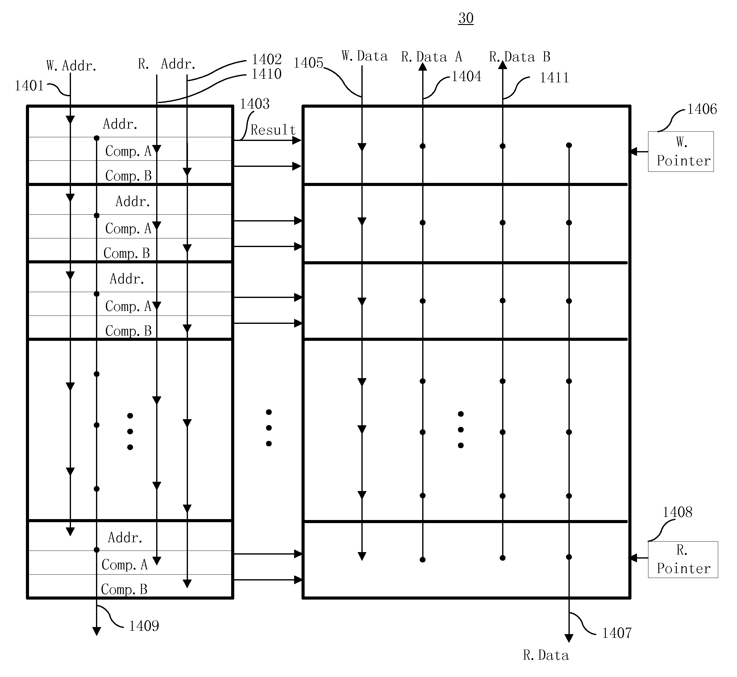
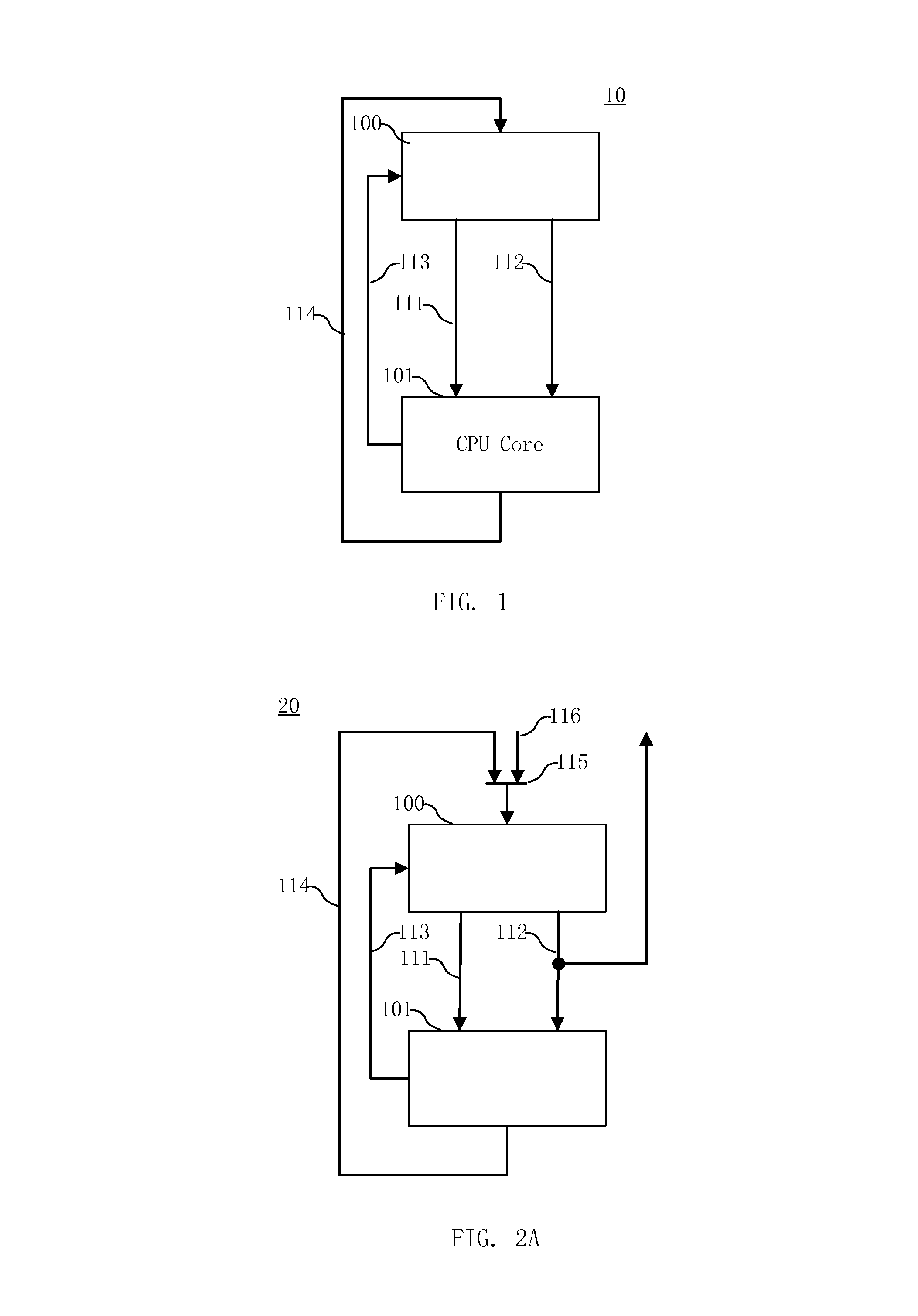
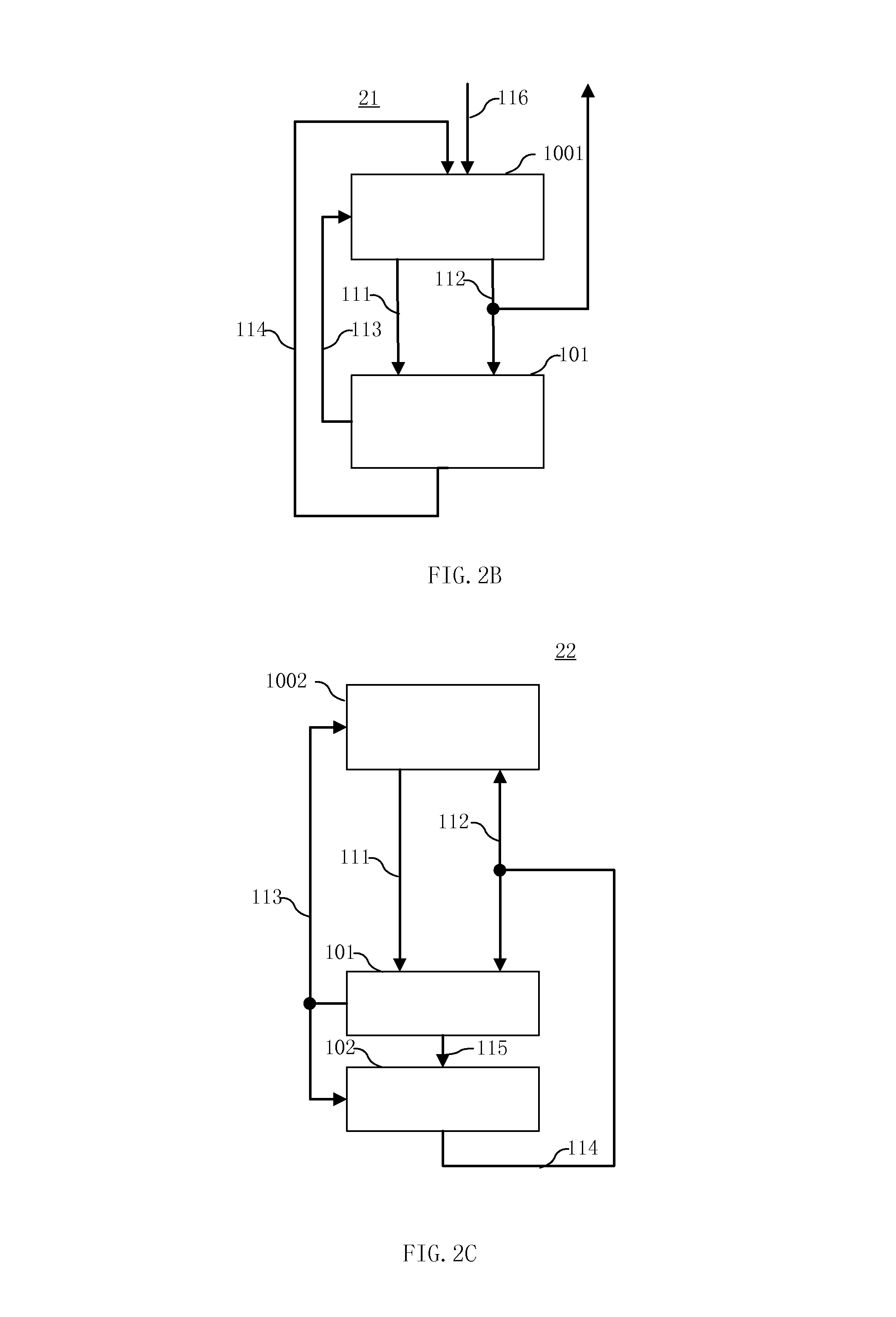
[0032]FIG. 1 illustrates an exemplary processor-cache structure 10 consistent with the disclosed embodiments. As shown in FIG. 1, processor-cache structure 10 includes a processor core 101 and a level-zero (L0) memory 100. Processor core 101 may include any appropriate processors or central processing unit (CPU) core, and the processor core 101 is coupled to the L0 memory 100 to obtain operands for operations. A level-zero or L0 memory, as used herein, refers to a memory coupled between the processor core 101 and a level-one memory or L1 cache, which is assumed as the lowest level in the memory hierarchy associated with the processor core 101. That is, the L1 cache is the closest memory to the processor core 101 in a conventional processor-cache struc...


PUM


Abstract

A digital system is provided. The digital system includes an execution unit, a level-zero (L0) memory, and an address generation unit. The execution unit is coupled to a data memory containing data to be used in operations of the execution unit. The L0 memory is coupled between the execution unit and the data memory and configured to receive a part of the data in the data memory. The address generation unit is configured to generate address information for addressing the L0 memory. Further, the L0 memory provides at least two operands of a single instruction from the part of the data to the execution unit directly, without loading the at least two operands into one or more registers, using the address information from the address generation unit.

Description

TECHNICAL FIELD[0001]The present invention generally relates to computer architecture and, more particularly, to the methods and systems for processor-cache processing.BACKGROUND ART[0002]In existing processor architectures, operands usually are loaded into registers from memory using a special ‘load’ instruction, and then sent to the execution unit for corresponding operations. After the execution is finished, the execution result is first stored in a register, and then written into memory from the register using a special ‘store’ instruction. Even for a processor able to obtain operands with direct memory addressing, due to the limitations on the number of memory ports and bandwidth, its execution unit cannot obtain all operands directly from the memory, but has to load certain operands from memory to registers. Thus, both memory and registers are used to provide all operands to the execution unit.[0003]On the other hand, a cache is often provided to duplicate a part of contents o...

Claims


Application Information

Patent Timeline
Patent Type & Authority Patents(United States)
IPC IPC(8): G06F9/34G06F9/30G06F12/08G06F12/0802
CPCG06F12/0802G06F9/30043G06F9/30098G06F9/34Y02B60/1225G06F9/3004G06F9/3013G06F9/355G06F9/3824G06F9/3826G06F9/383G06F9/3832Y02D10/00G06F9/30079G06F9/30145
Inventor LIN, KENNETH CHENGHAOREN, HAOQI
Owner SHANGHAI XINHAO MICROELECTRONICS
Learn More