Multistage force amplification of piezoelectric stacks

a piezoelectric stack and multi-stage technology, applied in piezoelectric/electrostrictive/magnetostrictive devices, piezoelectric/electrostriction/magnetostriction machines, electrical equipment, etc., can solve the problems of insufficient electric power harvesting, the inability of our soldiers to control the energy harvesting in military applications, and the inability to harvest enough electric power, etc., to achieve the effect of increasing the effective piezoelectric constant, increasing mechanical energy input stiff input p

Active Publication Date: 2015-06-02
NASA
View PDF31 Cites 19 Cited by
  • Summary
  • Abstract
  • Description
  • Claims
  • Application Information

AI Technical Summary

Benefits of technology

[0008]In view of the foregoing, it is an object of the invention to provide a system and method using multistage force amplification of piezoelectric energy harvesting transducers (MFAPEHTs). In this MFAPEHT, a multistage force amplification mechanism is employed to increase the effective piezoelectric constant and optimize the mechanical impedance match in order to increase mechanical energy input to the device with same mechanical vibration source. Aspects of MFAPEHTs may include a configuration that enables to amplify the input mechanical vibration force to more than one order of amplitude to apply every layer of the piezoelectric multilayer stacks. Further, a MFAPEHT can reduce the input stiffness of the PEHT to match the mechanical impedance of a mechanical vibration media and to increase the mechanical energy absorption from environments. In addition, the MFAPEHT structure can increase the effective piezoelectric constant in order of amplitudes. Moreover, the force amplification mechanism of the MFAPEHT may not affect the overall capacitance. Also, experimental data shows that the harvested electric power is proportional to the square of the amplitude of the force amplification when piezoelectric material working in linear range. Further, no share force is applied to the piezoelectric multilayer stack and compress stress is dominated in the MFAPEHT. Therefore, the MFAPEHT may have higher reliability and broad range of working stresses. Further, the same-sized MFAPEHT compared to a conventional PEHT, the MFAPEHT is capable to harvest electric power more than order of higher than a conventional PEHT. Also, the MFAPEHT can be used broadly for portable electronic devices for military and civilian applications such as aircraft, automobile and other transportation equipment to harvest waste mechanical energy and reduces noise.
[0009]In another embodiment of a MFAPEHT, relaxor piezoelectric single crystal multilayer stacks for energy harvesting transducers (RPSEHT), can also provide significant improvements over the current state of the art. Research developments have demonstrated that PMN-PT and PZN-PT relaxor single crystal materials have high piezoelectric constants (d33>1500 pC / N) and high electromechanical coupling factors (k33>88%) as well as advantageous cryogenic properties. Further, RPSEHT is capable of converting more than 50% of mechanical energy input into electrical energy out using relaxor piezoelectric single crystal materials, which possess greater than 80% mechanical-electrical coupling factors. In addition, the RPSEHT remains high energy conversion efficiency, i.e., high mechanical-electrical coupling factor, in a broad range of temperatures (from 70 C to at or near cryogenic temperatures). Moreover, the RPSEHT enable harvesting energy with high efficiency in both of off-resonance mode a resonance mode in a broad range of frequencies. Also, the RPSEHT structure increases the effective piezoelectric constant by an order of magnitude comparing with that of its piezo ceramic counterpart. The RPSEHT can harvest more electric charges compared to a single layer bulk relaxor piezoelectric single crystal of the same size given the same applied vibration motion force due to the high effective piezoelectric constraint of the RPSEHT. Further, the RPSEHT structure can increase the capacitance by order of magnitude such that it can translate into an increase in the energy storage capability and a reduction of magnitude in voltage. In addition, the RPSEHT structure can be scaled to any size and integrated into a vibration / motion system. Moreover, RPSEHT structure is more reliable and durable for applications in dynamic systems as well as portable electronic devices in military and civilian applications such as aircraft, automobiles, and other vehicles to harvest waste mechanical energy. Also, the RPSEHT may enable to reduce harmful vibration / noise significantly in various ranges of frequencies and temperature environments when applied.
[0010]In order to enhance the mechanical energy output to obtain high displacement, large mechanical load capability (high blocking force) and high displacement height ration with low applied voltage for actuator transducer, a secondary amplification of multiple flextensional actuations system (SAMFATS) is disclosed. The SAMFATS can provide several times larger displacement than a similarly sized flextensional actuator / transducer with the same level of mechanical load capability. Further, the SAMFATS has strong resonance for transducer applications. Moreover, the SAMFATS provides extremely high effective piezoelectric constant at resonance frequency and off-resonance frequencies. The effective piezoelectric constant can be controlled by varying the size of each component, the degree of the precurvature of the frames, the thickness of each layer in the multilayer stacks, and the piezoelectric materials used. In addition, the SAMFATS can offer high displacement height ratio (or effective device strain) as well as work in a broad temperature range (from Liquid nitrogen temperature to >100 C), and preferably in at least some embodiments at or near cryogenic conditions. Further, the performance of SAMFATS can always be improved by enhancing the piezoelectric material properties. In addition, a SAMFATS device enables future actuator designs and expands piezoelectric material applications.
[0013]Embodiments of the disclosure may also include methods for using a piezoelectric device, the method including steps for providing outer flextensional casing and a first cell and a last cell of a transducer coupled to the outer flextensional casing, each cell having a flextensional cell structure that includes a piezoelectric stack coupled to each flextensional cell structure of each cell. Such a method may also include receiving an input force at the first cell, amplifying the input force at the first cell to provide an output force for the first cell, receiving the output force of the first cell as the input force of the last cell, and amplifying the input force at the last cell to provide an output force for the last cell. Further, a first transducer output force is product of the input force of the first cell, the output force of the first cell, and the output force of the last cell. Additional steps in the method may include providing piezoelectric energy from the piezoelectric stack of each flextensional cell structure of each cell based on first transducer output force as well as providing displacement based on the first output transducer force. Further steps may include receiving the input force along a first axis at each flextensional cell structure and providing the output force along a second axis that is amplified compared to the first input force as well as reducing the stiffness of the transducer thereby increasing the amplification of the each input force for each cell and applying a voltage to each piezoelectric stack.

Problems solved by technology

Energy management is one of the most challenging issues in the world today.
Among them, heat and solar energies are weather dependent, which cannot be controlled by our soldiers for harvesting energy in military applications.
This is, obviously, the main reason why such conventional PEHTs cannot harvest enough electric power.

Method used


Image

  • Multistage force amplification of piezoelectric stacks
  • Multistage force amplification of piezoelectric stacks
  • Multistage force amplification of piezoelectric stacks

Examples


Embodiment Construction

[0023]In this section, the structure of a MFAPEHT and the multiple stages of force amplification mechanism are described first. The theoretical models for force amplification, piezoelectric constant amplification, and vibration energy harvesting for the MFAPEHT are developed. Then, the impedance issues to enhance the mechanical energy input to the MFAPEHT are briefly addressed. Finally, the experimental validation for MFAPEHT is presented.

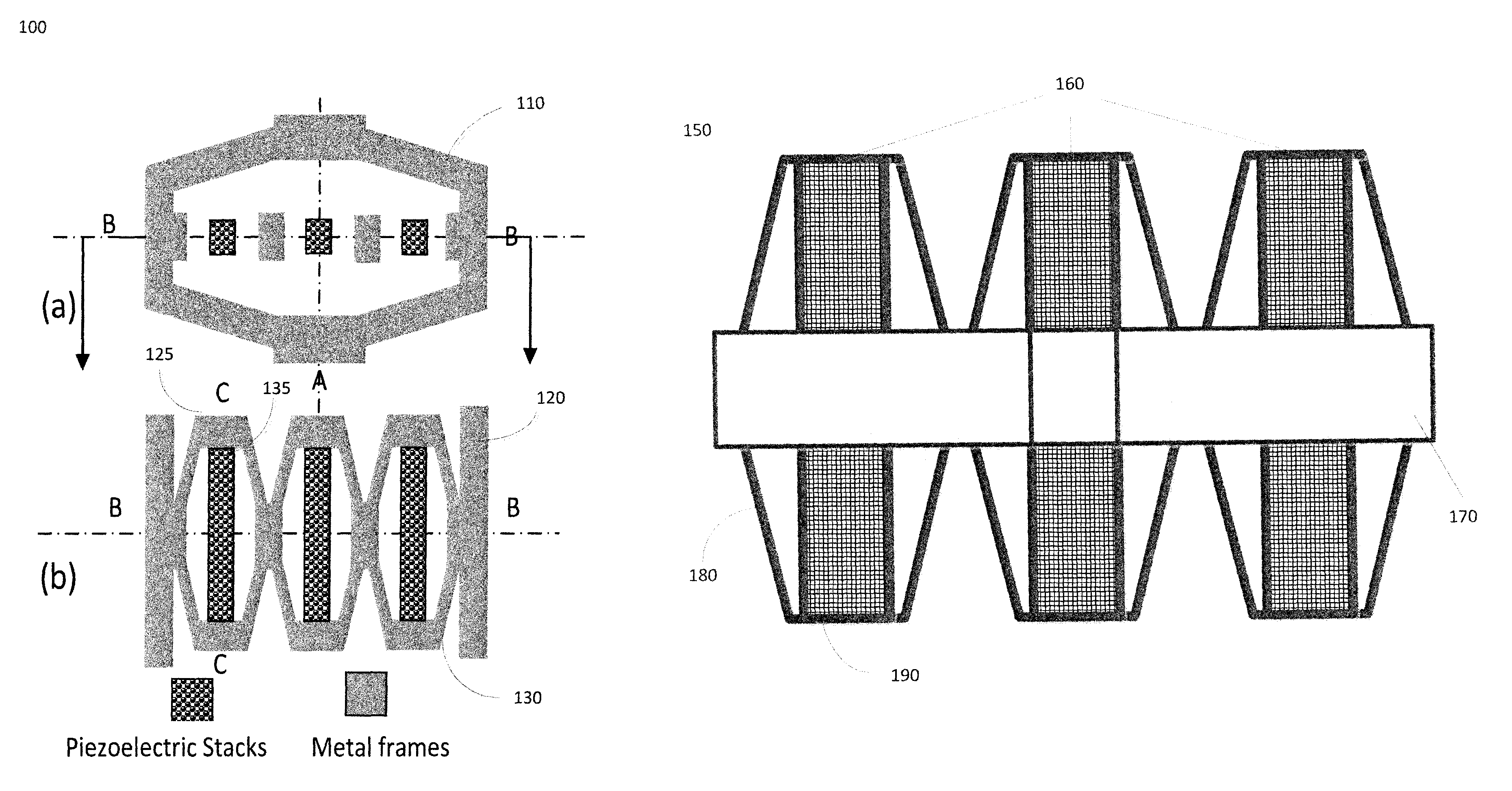
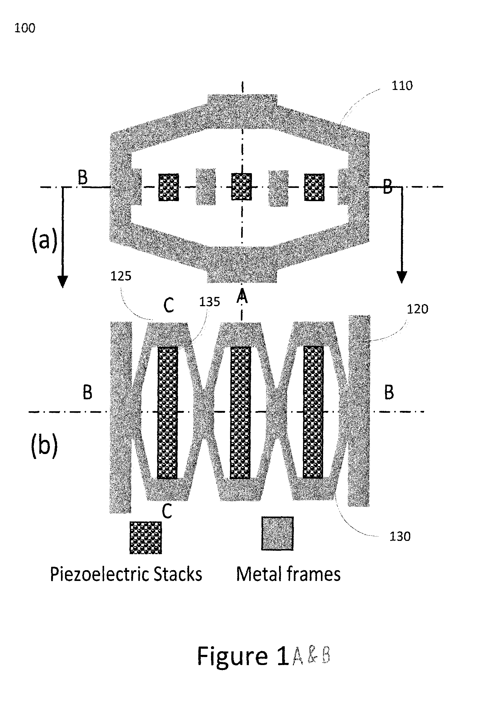
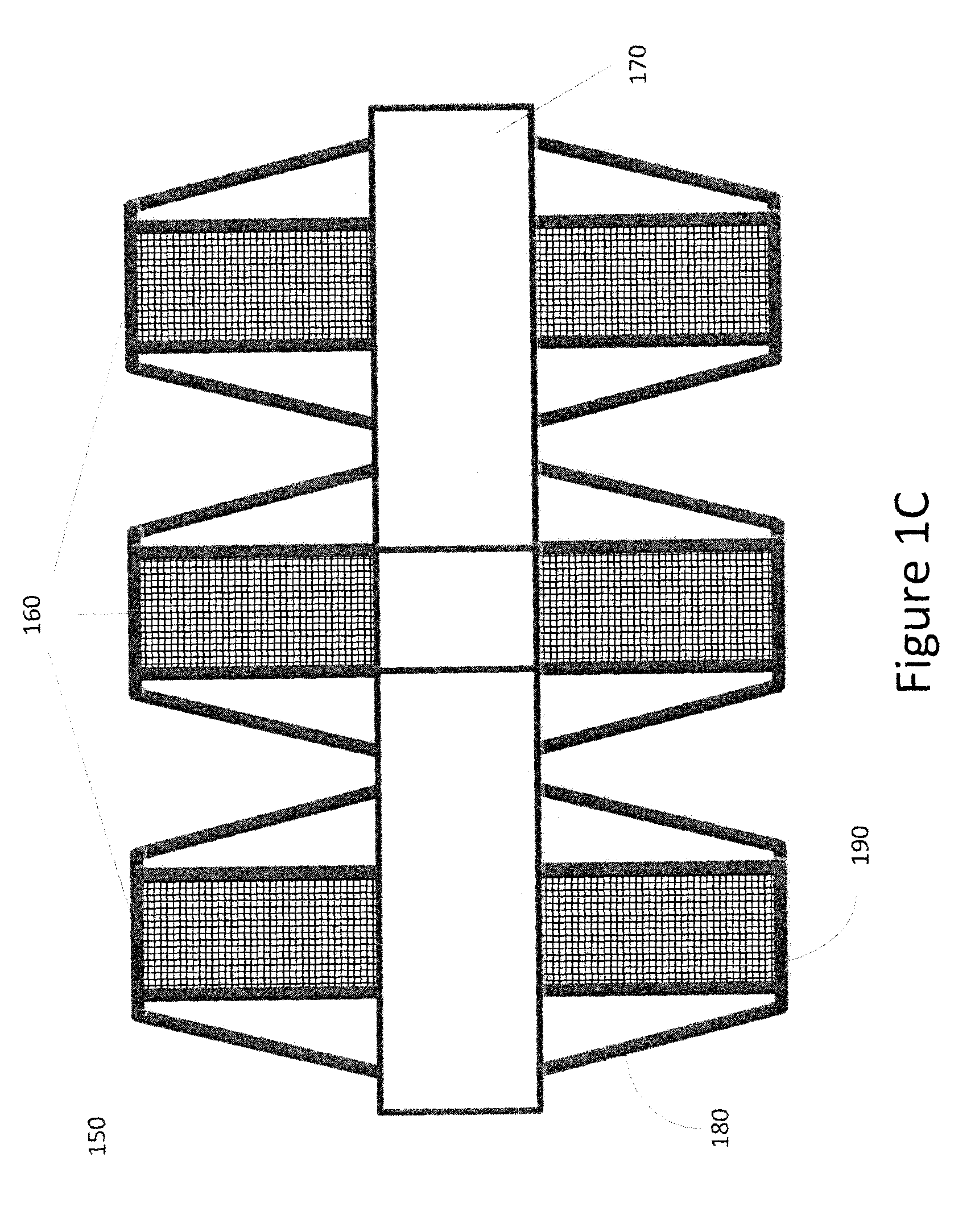
[0024]FIGS. 1A-C shows an exemplary two-stage force amplification of PEHT (TSFAPEHT) (100, 150). FIG. 1(a) is a front cross section view of the TSFAPEHT and FIG. 1(b) is a top cross section view. The TSAFAPEHT includes an outer flextensional casing structure 110 (120 viewed in the top cross section view in FIG. 1(b)that surrounds one or more cells 130. Each cell includes a flextensional cell structure 125 that may be made of a metal frame that surrounds a piezoelectric stack 135. In one embodiment the piezoelectric stack 135 may be a multilayer sta...


PUM


Abstract

Embodiments of the disclosure include an apparatus and methods for using a piezoelectric device, that includes an outer flextensional casing, a first cell and a last cell serially coupled to each other and coupled to the outer flextensional casing such that each cell having a flextensional cell structure and each cell receives an input force and provides an output force that is amplified based on the input force. The apparatus further includes a piezoelectric stack coupled to each cell such that the piezoelectric stack of each cell provides piezoelectric energy based on the output force for each cell. Further, the last cell receives an input force that is the output force from the first cell and the last cell provides an output apparatus force In addition, the piezoelectric energy harvested is based on the output apparatus force. Moreover, the apparatus provides displacement based on the output apparatus force.

Description

CROSS-REFERENCE TO RELATED APPLICATIONS[0001]This patent application relates to U.S. Provisional Patent Application No. 61 / 414,815, filed Apr. 15, 2010, and claims the benefits of U.S. Provisional Patent Application No. 61 / 414,807, U.S. Provisional Patent Application No. 61 / 414,803, and U.S. Provisional Patent Application No. 61 / 324,445 (all of which were filed Nov. 17, 2010), which are incorporated by reference.STATEMENT REGARDING FEDERALLY SPONSORED RESEARCH AND DEVELOPMENT[0002]This invention was made in part with Government support under Grant Number NCC-1-02043 awarded by the National Aeronautics and Space Administration. The Government may have certain rights in this invention.BACKGROUND OF THE INVENTION[0003]Energy management is one of the most challenging issues in the world today. Accordingly, various energy harvesting technologies have gained attention, including harvesting energy from walking or other vibration sources using piezoelectric materials. Self-powered supply so...

Claims


Application Information

Patent Timeline
Patent Type & Authority Patents(United States)
IPC IPC(8): H01L41/00H02N2/04H02N2/18
CPCH02N2/043H02N2/186
Inventor XU, TIAN-BINGSIOCHI, EMILIE J.ZUO, LEIJIANG, XIAONINGKANG, JIN HO
Owner NASA
Why Eureka
Try Eureka