Angularly stable device for mutually fixing a longitudinal carrier with a bone fixation element

a mutually stable, longitudinal carrier technology, applied in the field of angular stability devices for mutually fixing longitudinal carriers with bone fixation elements, can solve the problems of difficult realization, inability to lateral mount, relative cumbersomeness, etc., and achieve the effect of minimally invasive surgical technique, simple construction, and very flexible us

Active Publication Date: 2015-06-09
DEPUY SYNTHES PROD INC
View PDF20 Cites 2 Cited by
  • Summary
  • Abstract
  • Description
  • Claims
  • Application Information

AI Technical Summary

Benefits of technology

[0011]The invention is to provide a remedy here. It is an object of the invention to provide a device, which is very simple in construction, can be used very flexibly and permits a minimally invasive surgical technique.

Problems solved by technology

U.S. Pat. No. 4,920,959 of WITZEL ET AL. discloses an external fixator, which is relatively cumbersome.
Accordingly, a lateral mounting is not possible.
In free-hand use, particularly in percutaneous and minimally invasive use, this may be difficult to realize and represents a major disadvantage.
However, these open clamps all have the disadvantage that they require an additional element for their fixation.
However, the clamping screw has only this one function and is not constructed as a bone screw, which could fasten the whole construction to the bone.
The devices, known from the prior art, accordingly are quite complicated generally.

Method used


Image

  • Angularly stable device for mutually fixing a longitudinal carrier with a bone fixation element
  • Angularly stable device for mutually fixing a longitudinal carrier with a bone fixation element
  • Angularly stable device for mutually fixing a longitudinal carrier with a bone fixation element

Examples


Embodiment Construction

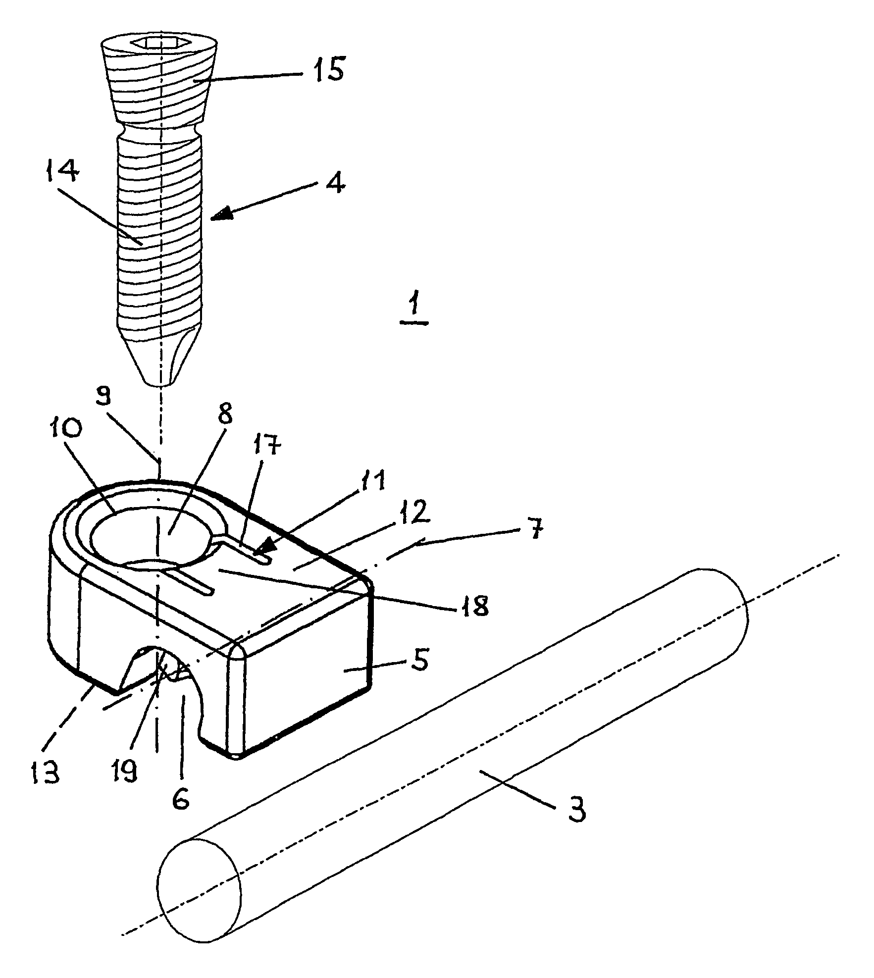
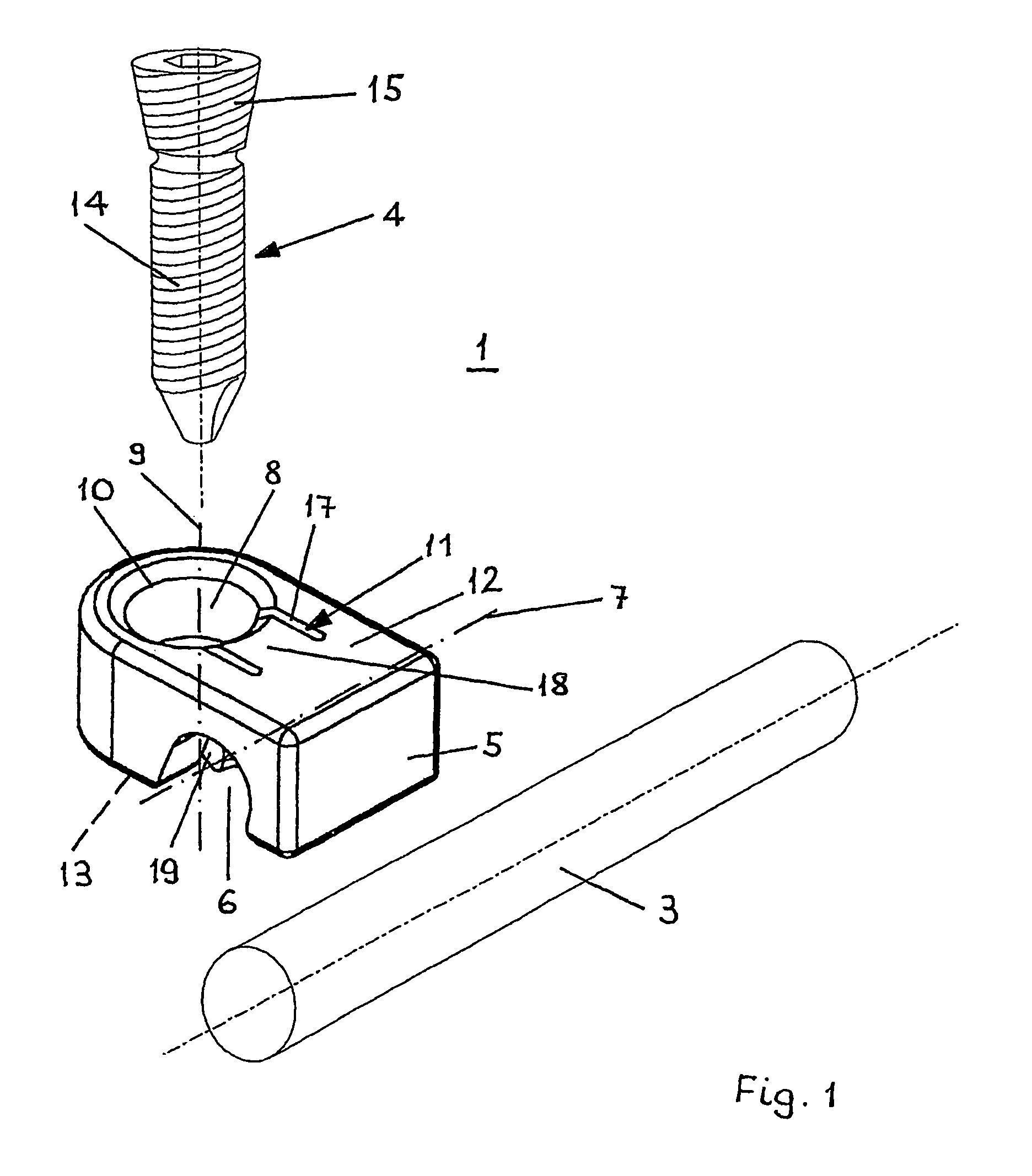
[0052]FIG. 1 shows an embodiment of the device 1 together with a bone fixation element 4, constructed as a bone screw, and a longitudinal carrier 3, the device 1 comprising essentially a 3-dimensional body 5 with a first surface 12 and, parallel thereto, a second surface 13. The three-dimensional body 5 serves as an element connecting the longitudinal carrier 3 and the bone fixation element 4 and comprises a borehole 8 with a borehole axis 9, which passes through the three-dimensional body 5 from the first surface 12 to the second surface 13 and is suitable for accommodating the bone fixation element 4. Furthermore, a channel 6, which is open towards the second surface 13, has an axis 7, which is perpendicular to the borehole axis 9 and is open in the direction of the second surface 13, so that a longitudinal carrier 3 can be introduced into the channel 6 transversely to the bone fixation element 4, passes through the three-dimensional body 5. The borehole 8 and the channel 6 are di...


PUM


Abstract

A device (1) for mutually fixing a longitudinal carrier (3) to a bone fixation element (4), wherein the device consists of a three-dimensional body (5) which has a channel (6) that is open on one side, wherein the axis of the channel (7) receives the longitudinal carrier (3), and a bore hole (8) that extends crosswise in relation to the axis of the channel (7) through the body (5) and that is provided with a wall (10). At least one part of the bore wall (10) disposed between the channel (6) and the bore hole (8) is embodied as an elastic element (11) which can be pressed into the region of the channel (6) by introducing the bone fixation element (4) into the bore hole (8), such that a longitudinal carrier (3) arranged in the channel can be firmly clamped in a rotational and longitudinal manner by said elastic element (11).

Description

CROSS-REFERENCE TO RELATED APPLICATION[0001]This Application is a national stage application under 35 U.S.C. 371 based on International Application Serial No. PCT / CH2005 / 000023 filed on Jan. 18, 2005 “ANGULARLY STABLE DEVICE FOR MUTUALLY FIXING A LONGITUDINAL CARRIER WITH A BONE FIXATION ELEMENT”.BACKGROUND OF THE INVENTION[0002]1. Field of the Invention[0003]The invention relates to a device of the introductory portion of claim 1.[0004]With such devices, it is possible to connect an appropriate connecting rod or a longitudinal carrier, as used in spinal column surgery, over a bone fixation element, preferably a bone screw, with the bone, in order to obtain a rigid construction.[0005]2. Description of the Related Art[0006]U.S. Pat. No. 4,920,959 of WITZEL ET AL. discloses an external fixator, which is relatively cumbersome. In particular, the individual clamp elements must be brought into position on the rods.[0007]The CH-A 632658 disclose an implant for fixing bones, for which the ...

Claims


Application Information

Patent Timeline
Patent Type & Authority Patents(United States)
IPC IPC(8): A61B17/70
CPCA61B17/7035A61B17/7049A61B17/7041A61B17/58A61B17/82A61B17/84A61B17/86
Inventor MATTHYS, ROMANO
Owner DEPUY SYNTHES PROD INC
Why Eureka
Try Eureka