Wide-area aerial camera systems

Active Publication Date: 2015-06-09
NEARMAP AUSTRALIA PTY LTD
View PDF12 Cites 30 Cited by
  • Summary
  • Abstract
  • Description
  • Claims
  • Application Information

AI Technical Summary

Benefits of technology

[0019]The pointing direction of a detail camera may be time-multiplexed via a beam-steering mechanism, the

Problems solved by technology

High overlap is therefore expensive, both in terms of flying time and processing time, and practical choices of overlap represent a compromise between cost and photomosaic accuracy.
An external pod has two key disadvantages: the pod is highly aircraft-specific, and space within the pod is constrained.
An aircraft-specific pod limits the choice of aircraft and the

Method used


Image

  • Wide-area aerial camera systems
  • Wide-area aerial camera systems
  • Wide-area aerial camera systems

Examples


Embodiment Construction

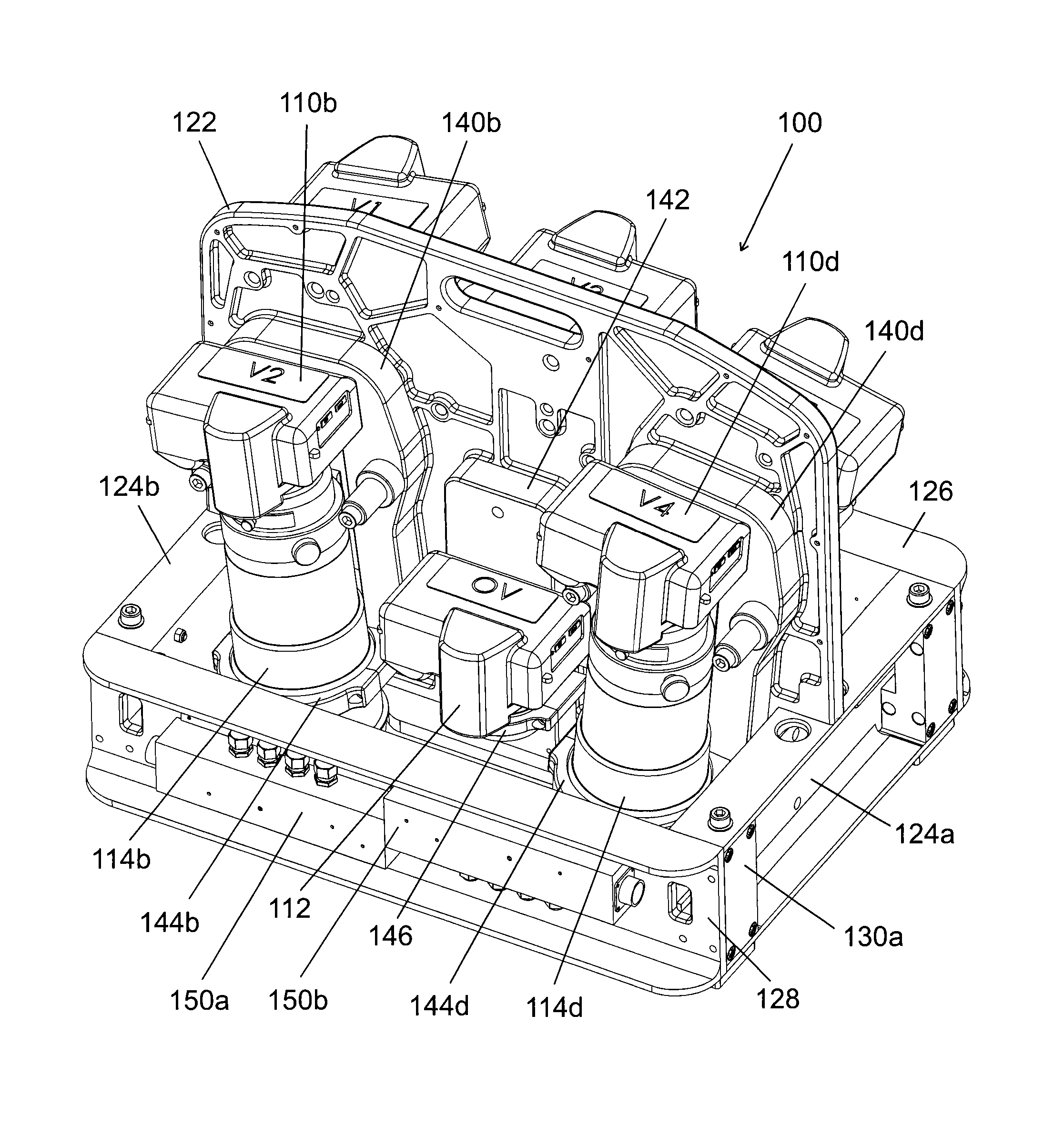
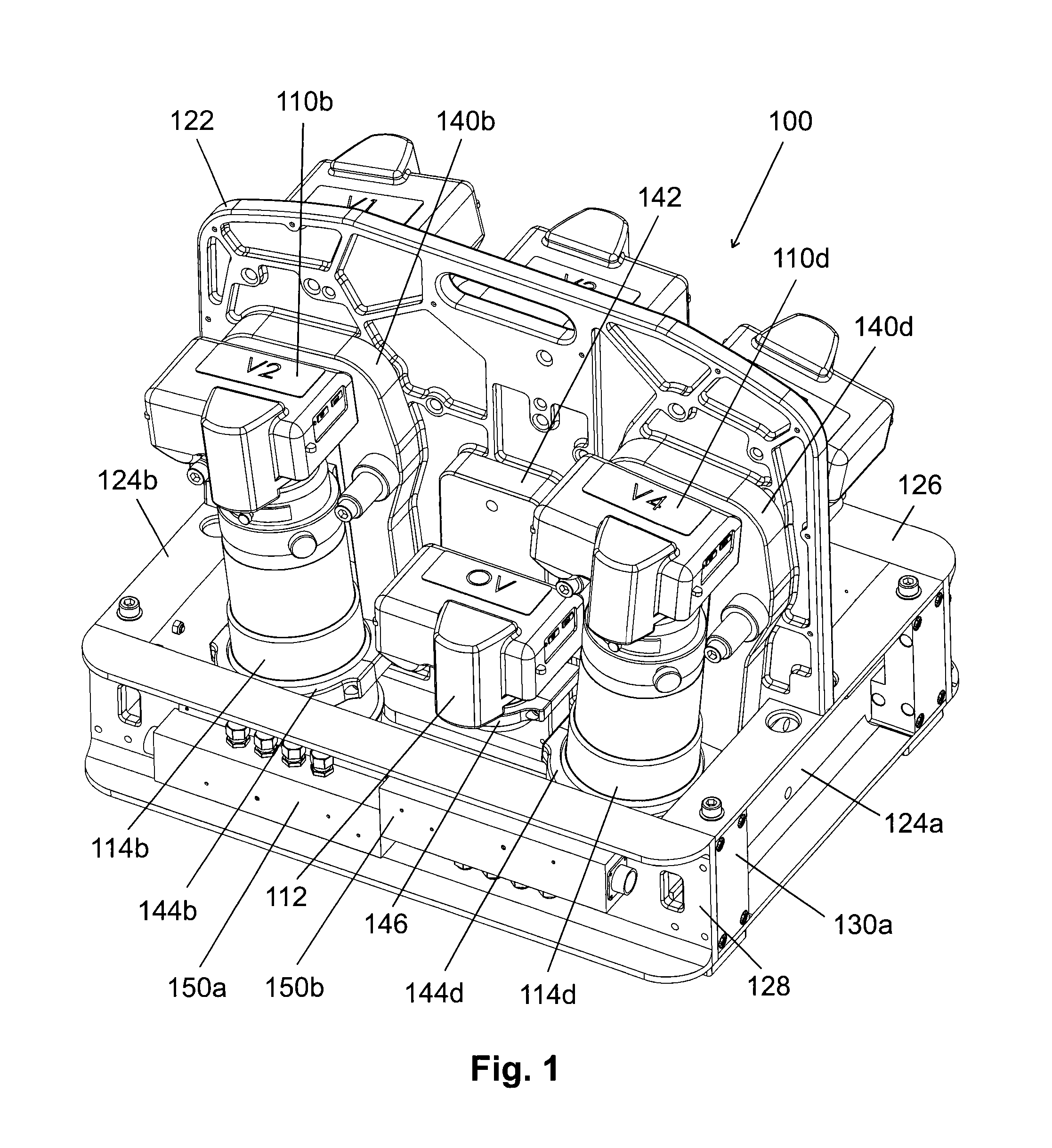
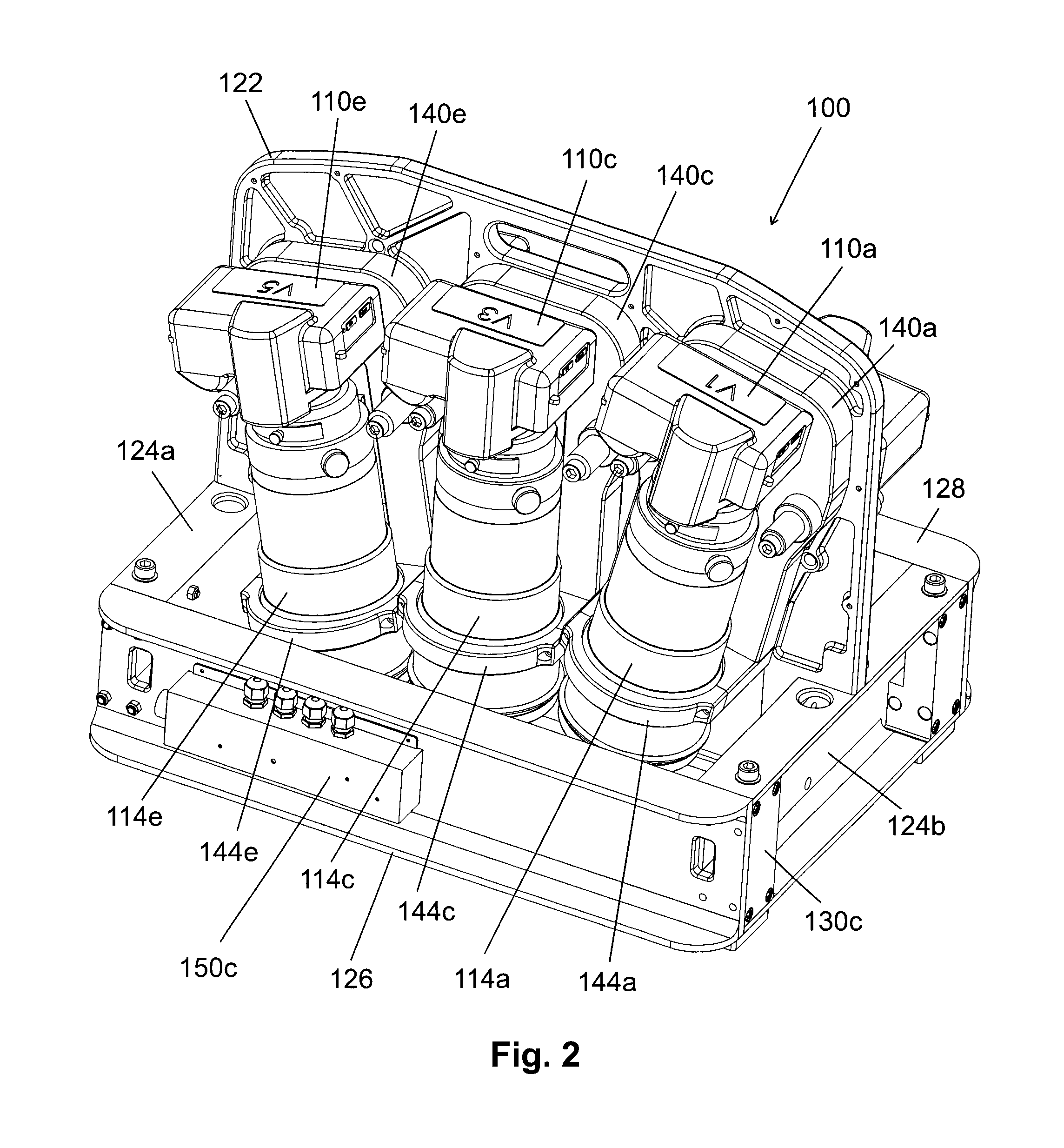
[0175]HyperCamera™ is a range of multi-resolution aerial camera systems suitable for deployment in a wide range of aircraft, large and small. The camera systems are modular, and designed to be installed above one or more standard camera holes where appropriate, as are typically provided through the floor of a survey aircraft or airborne pod.

[0176]Each HyperCamera model is defined by its pointing direction (P), the number of cameras (N) in its array, and the focal length (f) of the cameras, and is identified by the designator PN-f. For example, a 300 mm five-camera vertical HyperCamera is referred to as a V5-300 model.

[0177]The level of detail captured by an aerial camera is typically characterized by the ground sampling distance (GSD), i.e. the distance between adjacent pixel centers when projected onto the ground within the camera's field of view.

[0178]The GSD is determined by the focal length (252) of the camera lens, the altitude above ground level (254), and the pixel pitch (260...


PUM


Abstract

A system for capturing aerial images, the system comprising at least one camera unit, the camera unit comprising at least one overview camera, a plurality of detail cameras, and a frame for holding the cameras, each detail camera having a longer focal length than the at least one overview camera, each detail camera mounted at a different angle laterally so that the fields of view of the detail cameras overlap to form an extended lateral field of view.

Description

CROSS-REFERENCE TO RELATED APPLICATIONS[0001]This is a continuation-in-part of application Ser. No. 14 / 310,523, filed Jun. 20, 2014, the contents of which are incorporated herein by reference.FIELD OF THE INVENTION[0002]The present invention relates to efficient aerial camera systems and efficient methods for creating photomosaics from aerial photos.BACKGROUND OF THE INVENTION[0003]Accurately georeferenced photomosaics of orthophotos are becoming popular alternatives to traditional pictorial maps because they can be created automatically from aerial photos, and because they show actual useful detail on the ground.[0004]The creation of accurate photomosaics from aerial photos is well described in the literature. See, for example, Elements of Photogrammetry with Application in GIS, Fourth Edition (Wolf et al.), and the Manual of Photogrammetry, Sixth Edition (American Society for Photogrammetry and Remote Sensing (ASPRS)).[0005]The creation of a photomosaic requires the systematic cap...

Claims


Application Information

Patent Timeline
IPC IPC(8): G03B39/00G03B15/00G01C11/02
CPCG03B15/006G01C11/02G03B37/04H04N23/698H04N23/90G06T3/4038H04N7/181
Inventor LAPSTUN, PAULTARLINTON, MARK HAROLDBLEADS, DAVID ARNOLD
Owner NEARMAP AUSTRALIA PTY LTD
Why Eureka
Try Eureka