Compliant printed circuit area array semiconductor device package

a semiconductor device and printed circuit technology, applied in semiconductor devices, semiconductor/solid-state device details, electrical apparatus, etc., can solve the problems of difficult repair, inability to connect ic devices to final pcbs, and small size and distance between die terminals, and achieve excellent electrical performance and low cos

Active Publication Date: 2015-06-09
KONINKLIJKE PHILIPS ELECTRONICS NV +1
View PDF429 Cites 9 Cited by
  • Summary
  • Abstract
  • Description
  • Claims
  • Application Information

AI Technical Summary

Benefits of technology

[0009]The present application relates to a compliant array IC device package (IC package). The present IC package is inexpensive to produce, has relative long life and provides excellent electrical performance.
[0010]The present disclosure can leverage the capabilities of the additive printing process to provide a high performance IC package capable of interconnecting a single device or multiple IC devices, while providing at or near terminal compliance to increase interconnect reliability. The unique nature of the additive printing process allows for a direct writing of circuitry and dielectrics, with the added benefit of stress decoupling at the terminal joints as well as embedded function not seen in traditional IC packaging. The additive printing process allows for packaging that provides very high frequency performance, as well as the addition of on-board electrical devices and circuitry planes that are not available with other IC packages.
[0011]The use of additive printing processes permits the material set in a given layer to vary. Traditional PCB and circuit fabrication methods take sheets of material and stack them up, laminate, and / or drill. The materials in each layer are limited to the materials in a particular sheet. Additive printing technologies permit a wide variety of materials to be applied on a layer with a registration relative to the features of the previous layer. Selective addition of conductive, non-conductive, or semi-conductive materials at precise locations to create a desired effect has the major advantages in tuning impedance or adding electrical function on a given layer. Tuning performance on a layer by layer basis relative to the previous layer greatly enhances electrical performance.
[0012]The production cost for the IC packages in accordance with the present disclosure can be a fraction the cost of producing existing IC packages. The use of additive printing processes, such as for example to print electrical features, can reduce capital cost and lead time for building the present IC packages. The additive printing processes also increase production yields over conventional IC packages that rely on conventional lithography tools and masks.
[0013]Internal compliance of the interconnect assembly in the present IC package can greatly increase performance over conventional IC packages. The ability to build multi-layer structures over a relatively large area permits terminal pitch on the IC devices to be reduced. The addition of circuitry planes and electrical devices in the present IC package provides performance enhancements not available with current IC packages. The ability to add electrical devices, such as transistors and memory, to the present IC package provides the opportunity to incorporate intelligence directly into the package.

Problems solved by technology

In many cases, the size and distance between die terminals is so small that the IC device cannot be connected to the final PCB without some sort of re-routing interface.
Regardless of whether a package is under filled with epoxy, the connection of the IC device to the package is generally not reworkable after packaging, and if there is a missing or broken connection it is difficult to repair.
If the packaged IC device fails testing then the cost of the package and manufacturing process is lost.
In general, the area array packaging is more expensive due to the larger pin counts and more sophisticated substrates required.
The limitations for area array packaging include the terminal pitch, thermal management, cost, ability to rework faulty IC devices and reliability of the solder joints.
There also has been advancements in recent years in both area array packaging and peripheral lead packaging where multiple IC devices are placed in the same package, creating what has been nicknamed SiP for “system in package.” Placing multiple IC devices in a single package further complicates the problems discussed above.

Method used


Image

  • Compliant printed circuit area array semiconductor device package
  • Compliant printed circuit area array semiconductor device package
  • Compliant printed circuit area array semiconductor device package

Examples


Embodiment Construction

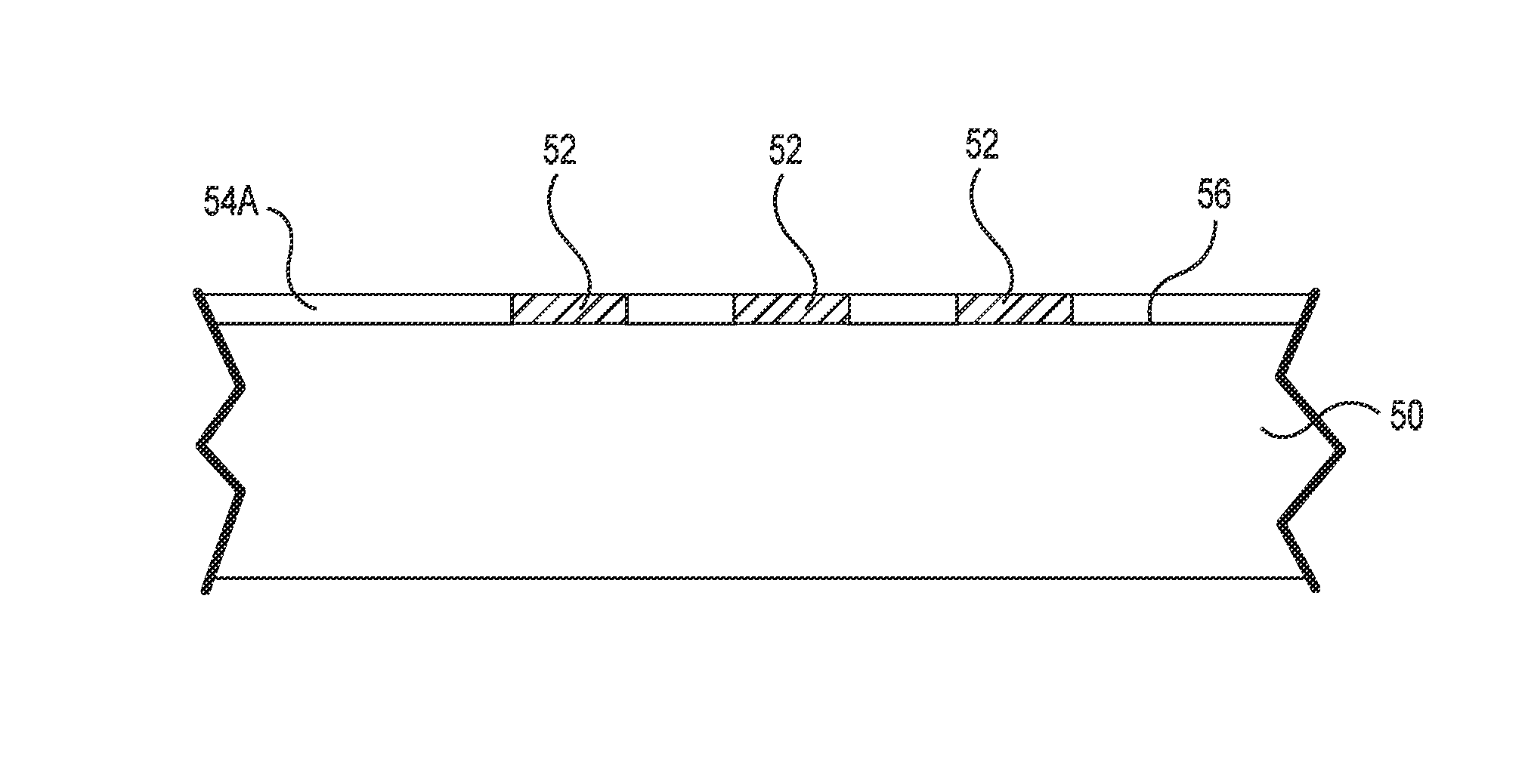
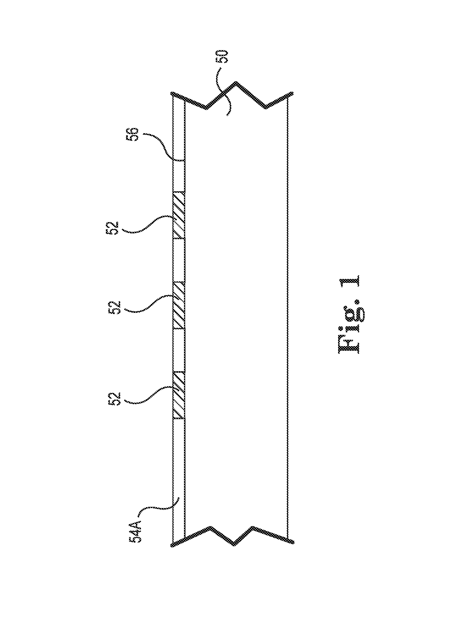
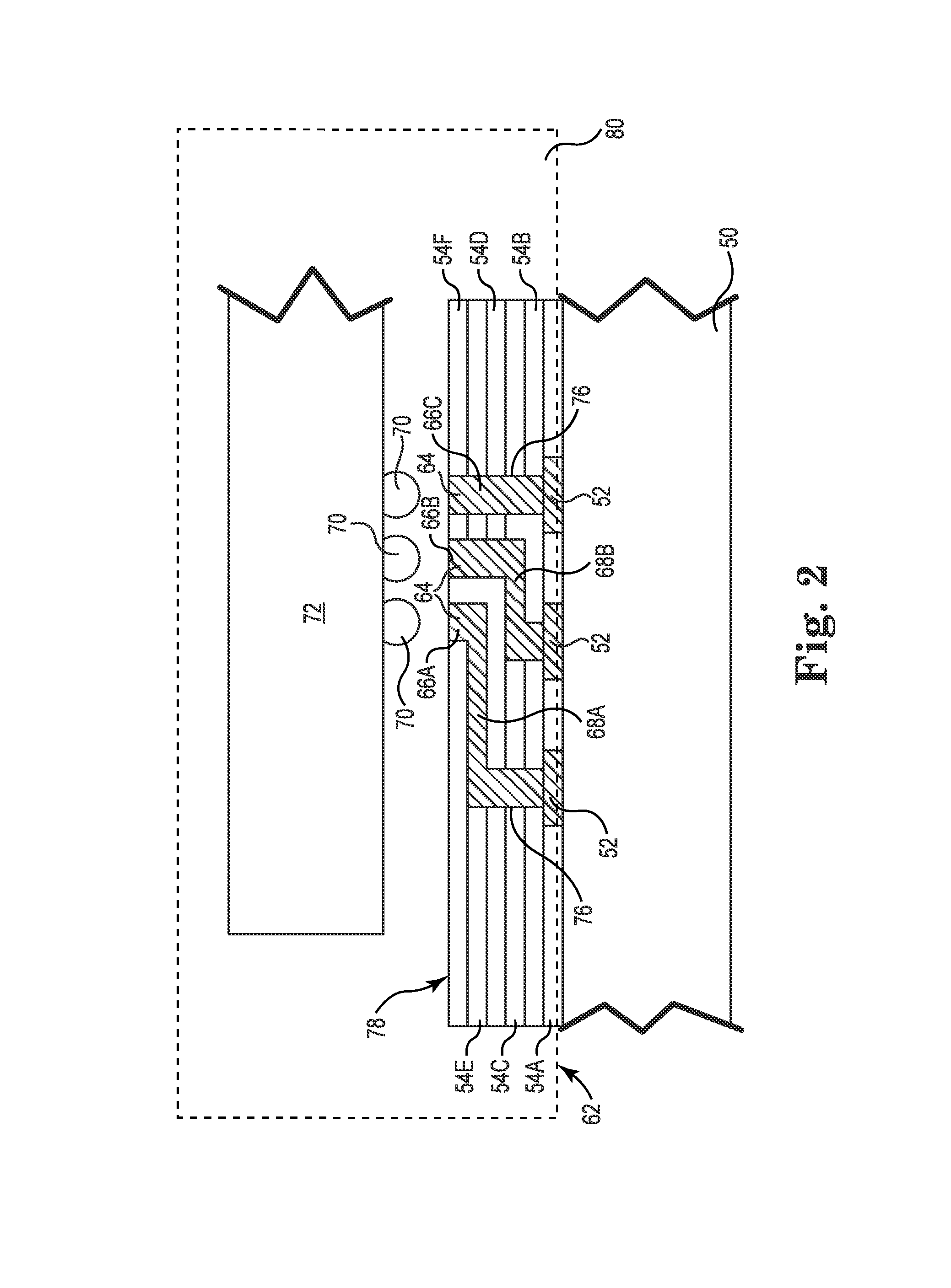
[0040]The present disclosure is directed to a compliant array IC package that is inexpensive to produce, has relative long life and provides excellent electrical performance. An IC package according to the present disclosure can be formed by an additive printing process to provide a high performance IC package capable of interconnecting a single device or multiple IC devices, while providing at or near terminal compliance to increase interconnect reliability. The unique nature of the additive printing process can allow direct writing of circuitry and dielectrics, while also allowing stress decoupling at the terminal joints as well as embedded function not seen in traditional IC packaging.

[0041]Printable silicon inks provide the ability to print electrical devices. Exemplary embodiments of printable silicone inks are disclosed, for example, in U.S. Pat. No. 7,485,345 (Renn et al.); U.S. Pat. No. 7,382,363 (Albert et al.); U.S. Pat. No. 7,148,128 (Jacobson); U.S. Pat. No. 6,967,640 (A...


PUM


Abstract

An integrated circuit (IC) package for an IC device, and a method of making the same. The IC package includes an interconnect assembly with at least one printed compliant layer, a plurality of first contact members located along a first major surface, a plurality of second contact members located along a second major surface, and a plurality of printed conductive traces electrically coupling a plurality of the first and second contact members. The compliant layer is positioned to bias at least the first contact members against terminals on the IC device. Packaging substantially surrounds the IC device and the interconnect assembly. The second contact members are accessible from outside the packaging.

Description

CROSS-REFERENCE TO RELATED APPLICATIONS[0001]This application is a national stage application under 35 U.S.C. §371 of International Application No. PCT / US2010 / 036363, titled COMPLIANT PRINTED CIRCUIT AREA ARRAY SEMICONDUCTOR DEVICE PACKAGE, filed May 27, 2010, which claims priority to U.S. Provisional Application No. 61 / 183,411, filed Jun. 2, 2009, both of which are hereby incorporated by reference in their entireties.TECHNICAL FIELD[0002]The present disclosure relates to a compliant array integrated circuit (IC) device package, and in particular, to a compliant IC device package made using an additive printing process.BACKGROUND OF THE INVENTION[0003]Traditional semiconductors and IC devices are typically formed on a substrate using photolithography. The substrate may be a silicon wafer. Multiple IC devices are typically formed on a single wafer and then the wafer is cut into die. The IC devices are typically packaged in a variety of ways to provide redistribution from the terminal...

Claims


Application Information

Patent Timeline
Patent Type & Authority Patents(United States)
IPC IPC(8): H01L23/538H01L23/552H01L21/48H01L23/498H01L23/66H01L23/00
CPCH01L23/4985H01L21/4867H01L23/552H01L23/66H01L24/90H01L23/49822H01L24/16H01L2221/68345H01L2223/6677H01L2924/01013H01L2924/01029H01L2924/01049H01L2924/01078H01L2924/01079H01L2924/01082H01L2924/09701H01L2924/12044H01L2924/14H01L2924/15174H01L2924/19041H01L2924/19042H01L2924/19043H01L2924/3011H01L2924/3025H01L2924/01006H01L2924/01033H01L2924/01047H01L2924/01075H01L2924/014H01L2225/06527H01L2225/06517H01L2225/06572H01L2224/81191H01L2924/1306H01L2224/16235H01L2924/00H01L2924/15787H01L2224/0557H01L2224/05573H01L2924/00014H01L2224/05571H01L2224/0554H01L2224/05599H01L2224/0555H01L2224/0556
Inventor RATHBURN, JAMES
Owner KONINKLIJKE PHILIPS ELECTRONICS NV
Why Eureka
Try Eureka