Eureka AIR delivers breakthrough ideas for toughest innovation challenges, trusted by R&D personnel around the world.

Food processing vat with zoned temperature control

a technology of temperature control and food processing, which is applied in the direction of milk receptacles, cheese manufacture, milking devices, etc., can solve the problems of overheating or overcooling of food layers running down the splash zone, and achieve the effect of less heating and vastly different materials and/or processes

Active Publication Date: 2015-06-16
CHEESE SYST
View PDF32 Cites 0 Cited by
  • Summary
  • Abstract
  • Description
  • Claims
  • Application Information

AI Technical Summary

Benefits of technology

[0008]In accordance with one aspect of the invention, a vat is provided that includes a bottom wall, side walls extending upwardly from the bottom wall, and a zoned heat transfer system for selectively transmitting heat to or removing heat from different portions of at least one of the bottom and side walls of the vat. The zoned heat transfer system may include at least one lower heat transfer zone and at least one upper heat transfer zone. The lower heat transfer zone may extend across the vat bottom wall and the upper heat transfer zone may extend across each of the vat side walls. This allows less heating or less cooling to occur in portions of the vat that are more susceptible to overheating or overcooling the vat contents.
[0009]In accordance with another aspect of the invention, multiple lower and / or multiple upper heat transfer zones may extend across the vat lower and side walls, respectively. The multiple lower and / or upper heat transfer zones may include at least a pair of lower and a pair of upper heat transfer zones. In one embodiment, intermediate heat transfer zones are provided between the lower and upper heat transfer zones. Respective pairs of the heat transfer zones may be controlled separately with respect to other pairs of the heat transfer zones. The two heat transfer zones of each simultaneously controlled pair may be provided at opposite side walls of the vat, so that by controlling the respective pairs of zones, temperature changes along the height of the vat are mirrored on both sides of the vat, as a reflection about a longitudinally extending centerline of the vat. In another embodiment, each of the multiple heat transfer zones may be controllable separately with respect to the other heat transfer zones, and / or in pairs with respect to other pairs of heat transfer zones. Separate controllability of heat transfer activity of the various heat transfer zones may help control instances of overheating or overcooling that may occur at about the same height on different walls of the vat.
[0010]In accordance with another aspect of the invention, transmitting heat to or removing heat from different portions of the vat is accomplished by circulating a heat transfer fluid through the zoned heat transfer system. The heat transfer fluid may be heated for transmitting heat to the at least one of the bottom and side walls of the vat and / or unheated, optionally cooled, for removing heat from the at least one of the bottom and side walls of the vat. A diverter system may direct flow of the heat transfer fluid through the zoned heat transfer system. The diverter system selectively may direct the heat transfer fluid to flow through various heat transfer zones and prevent the heat transfer fluid from flowing through other heat transfer zones, based on the requirements for processing a particular batch of food product, which may provide for a substantial amount of control and tunability to the heat transfer system so that the vat can accommodate vastly different materials and / or processes.
[0011]In accordance with another aspect of the invention, the heat transfer zones are connected to each other in series, such that a heat transfer fluid flows sequentially through the respective heat transfer zones, and the diverter system controls which one(s) of the heat transfer zones that the heat transfer fluid can flow through. Additionally or instead, the heat transfer zones may be connected to each other in parallel, such that a heat transfer fluid is divided and simultaneously flows through the respective heat transfer zones. Each of the heat transfer zones may include a heat exchanger and the respective inlets and outlets of the heat exchangers may be connected to each other, with intervening diverters of the diverter system, so as to establish the series and / or parallel connections of the heat transfer zones, allowing for control versatility to accommodate different materials and / or processes.
[0012]In accordance with another aspect of the invention, a method of processing food in a vat includes determining (i) a target size of a batch of food product to be processed in a vat, and (ii) a target temperature for processing the batch of food product within the vat. A heat transfer fluid is delivered to a zoned heat transfer system of the vat for transmitting heat to or removing heat from the batch of food product and is directed through the zoned heat transfer system along a flow path that is selected based on at least one of the target size and target temperature of the batch of food product. A temperature differential may be established between two heat transfer zones of the heat transfer system. A temperature of one of the two heat transfer zones may be heated or cooled to a temperature that defines a first component of the temperature differential, which substantially corresponds to the target temperature for processing the batch of food, allowing for control versatility to accommodate different batches while reducing the likelihood of overheating or overcooling layers of the food that may be running down the splash-zone toward the rest of the food.

Problems solved by technology

The inventors have further recognized that in temperature controlled vats, the splash-zone tends to heat or cool the food layers running down them more quickly than the main mass of food that is heated or cooled by the corresponding portion of the vat, which may lead to overheating or overcooling of the food layers running down the splash-zone.

Method used


Image

  • Food processing vat with zoned temperature control
  • Food processing vat with zoned temperature control
  • Food processing vat with zoned temperature control

Examples


Embodiment Construction

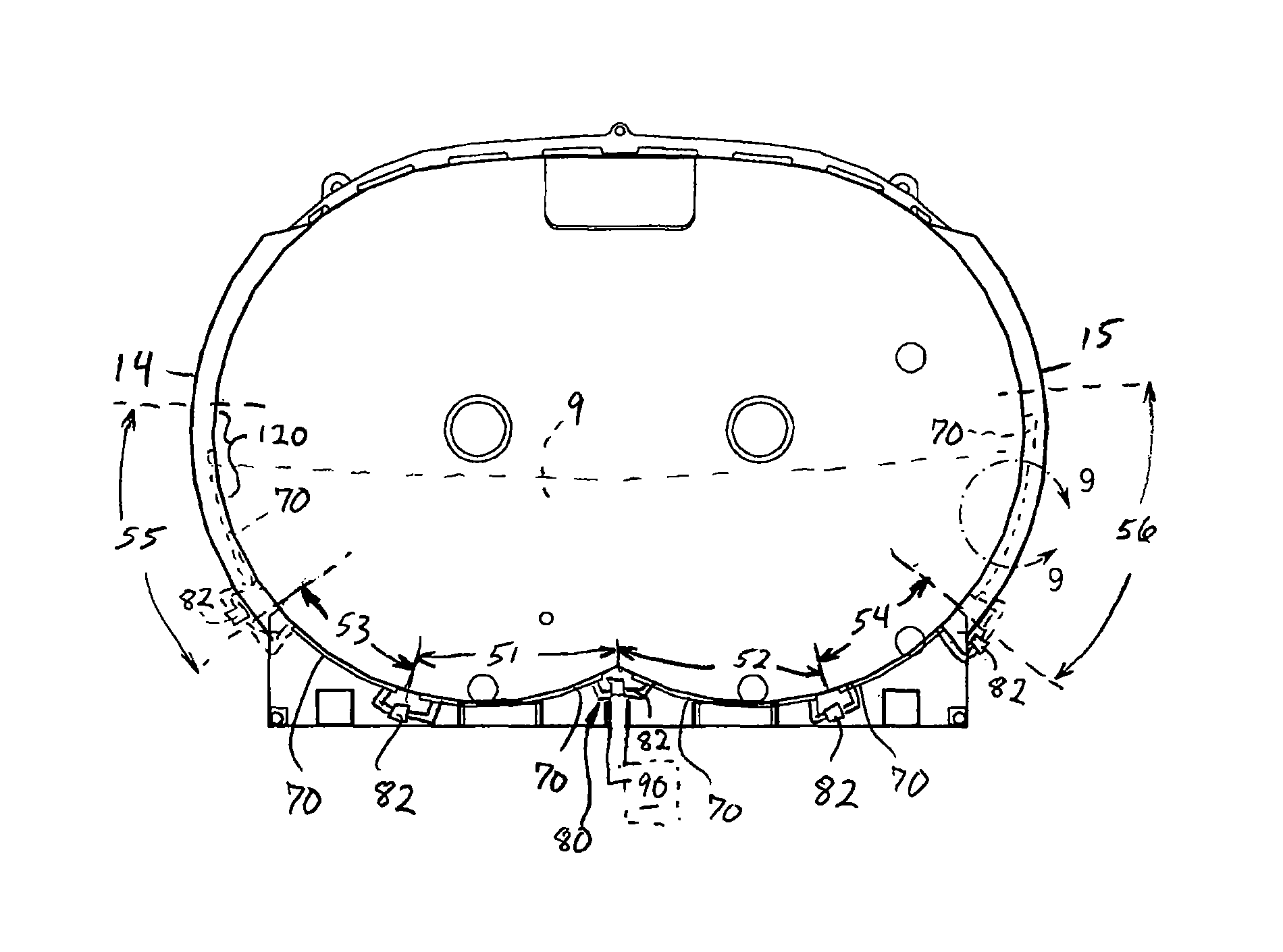
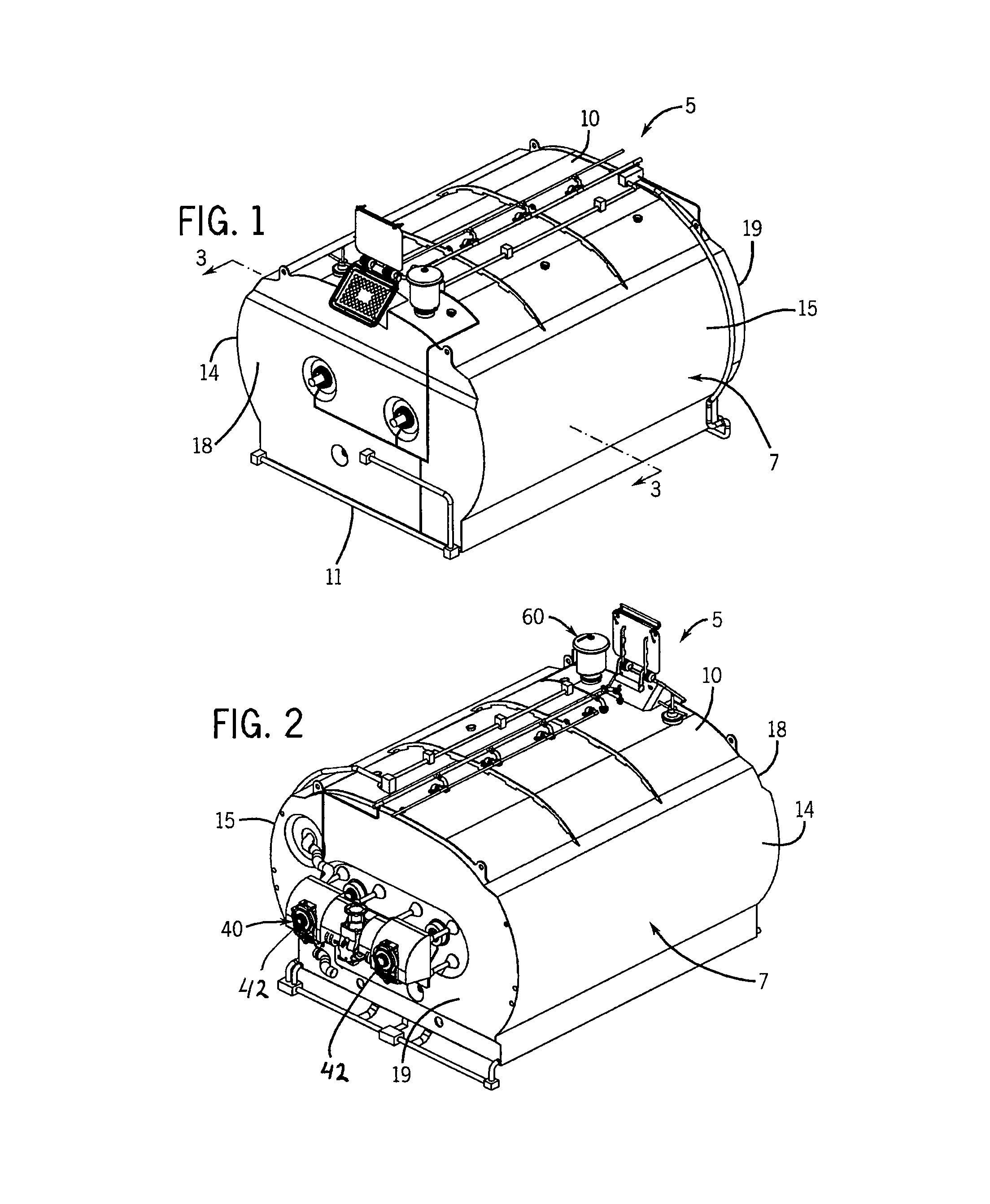
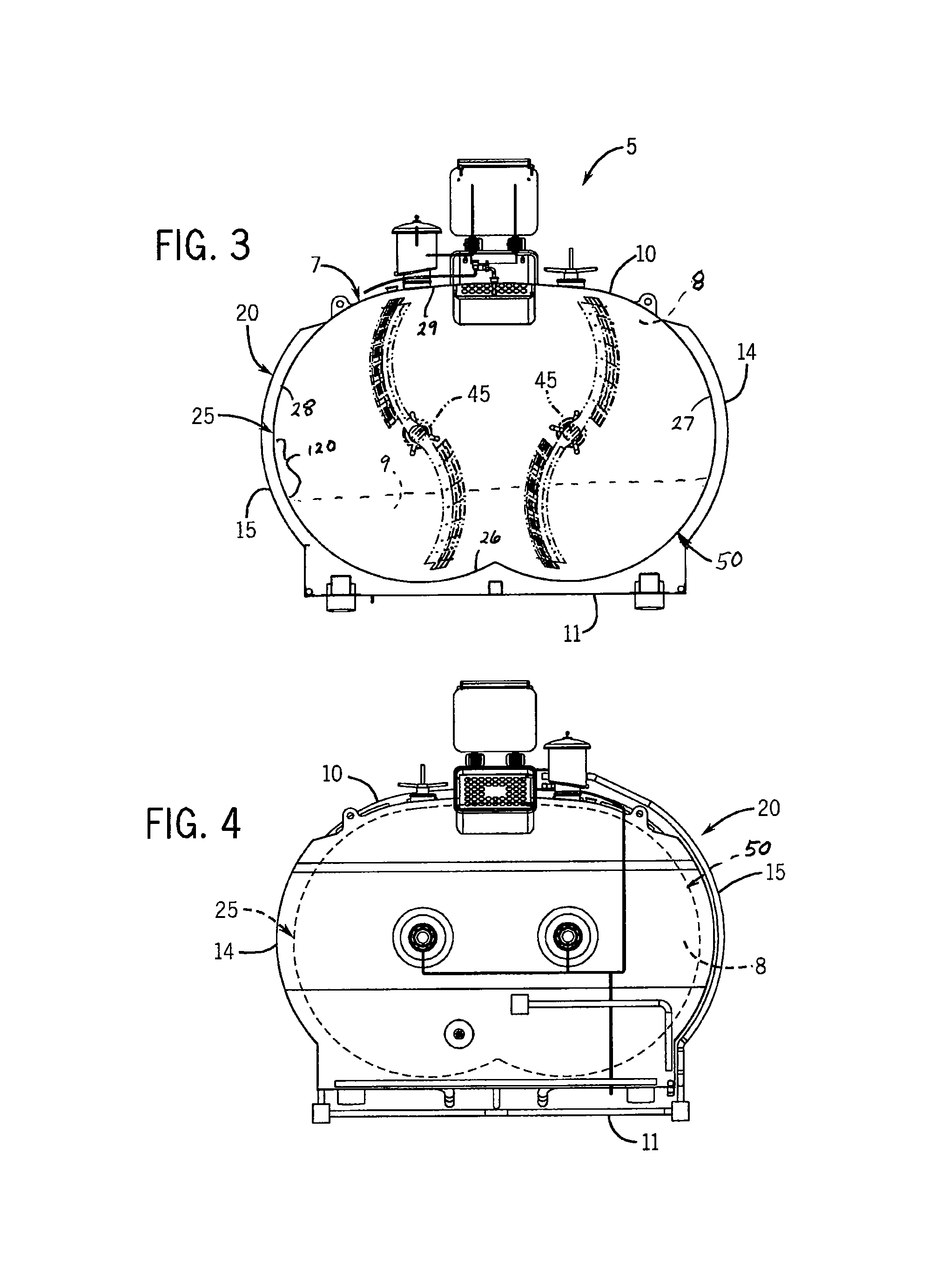
[0027]FIGS. 1 and 2 illustrate a vat system 5 that can be used for processing food and related products (collective referred to as “vat contents 9”) by mechanically manipulating and heating or cooling the vat contents 9, depending on the particular food or related product being processed. In a representative application, the vat system 5 may be used in the production of cheese, although it is understood that the vat system 5 may be used in processing other types of food products. It is also understood that the vat system 5 may be used for processing non-food liquid or semi-liquid compositions. The vat system 5 includes a vat 7 that has an agitation system 40 which performs the mechanical manipulations tasks by delivering power through a pair of drives 42 (FIG. 2) that rotate a pair of shafts 45 (FIG. 3) upon which blade assemblies are mounted, and a zoned heat transfer system 50 to perform such heating and / or cooling to provide zoned temperature control to the vat 7.

[0028]Referring ...


PUM


Abstract

A food processing vat is provided with a zoned heat transfer system that provides zoned temperature control to the vat. The zoned heat transfer system selectively transmits heat to or removes heat from different portions of a bottom wall and / or side wall(s) of the vat. A heat transfer fluid may be directed through the zoned heat transfer system along a flow path that is selected based on a target size and / or a target temperature of a batch of food product being processed in the vat.

Description

CROSS-REFERENCE TO RELATED APPLICATIONS[0001]This application claims priority from U.S. Provisional Patent Application Ser. No. 61 / 325,612 filed on Apr. 19, 2010, the entirety of which is expressly incorporated by reference herein.BACKGROUND OF THE INVENTION[0002]1. Field of the Invention[0003]The invention relates to food processing vats and, more particularly, to temperature control systems of food processing vats.[0004]2. Discussion of the Related Art[0005]Temperature control systems for use in food processing vats are known in the food processing industries. Such systems are widely used in equipment for processing liquid or semi-liquid food products, such as cheese vats.[0006]Temperature control systems used in cheese vats typically have hollow jackets that cover sidewalls of the vat. Steam, heated liquid, or cool liquid is introduced into the jacket. Introducing steam or heated liquid into the jacket warms the sidewalls of the vat and thus also warms the vat contents. Introduci...

Claims


Application Information

Patent Timeline
Patent Type & Authority Patents(United States)
IPC IPC(8): A47J39/00A01J9/04A23L3/16A01J25/00A23C19/00A23L3/00
CPCA01J25/001A01J9/04A23L3/003A23L3/16A01J25/02A23C3/031A23L3/363A23L3/001A23C3/045A23C19/0976A23C19/0973A23C19/00
Inventor ISENBERG, TIMOTHY J.ZIRBEL, JOHN E.
Owner CHEESE SYST
Why Eureka
Eureka Blog
Learn More