
Flexible stent-graft

a flexible, stent technology, applied in the field of stent grafts, can solve the problems of reducing the usefulness and applicability of existing stent grafts, affecting the flexibility of stent grafts, and reducing the usefulness of stent grafts for certain procedures, so as to improve flexibility, reduce endoleakage, and enhance the fixation of the vessel wall

Active Publication Date: 2015-06-16
SHANGHAI MICROPORT ENDOVASCULAR MEDTECH (GRP) CO LTD
View PDF55 Cites 2 Cited by
  • Summary
  • Abstract
  • Description
  • Claims
  • Application Information

AI Technical Summary

Benefits of technology

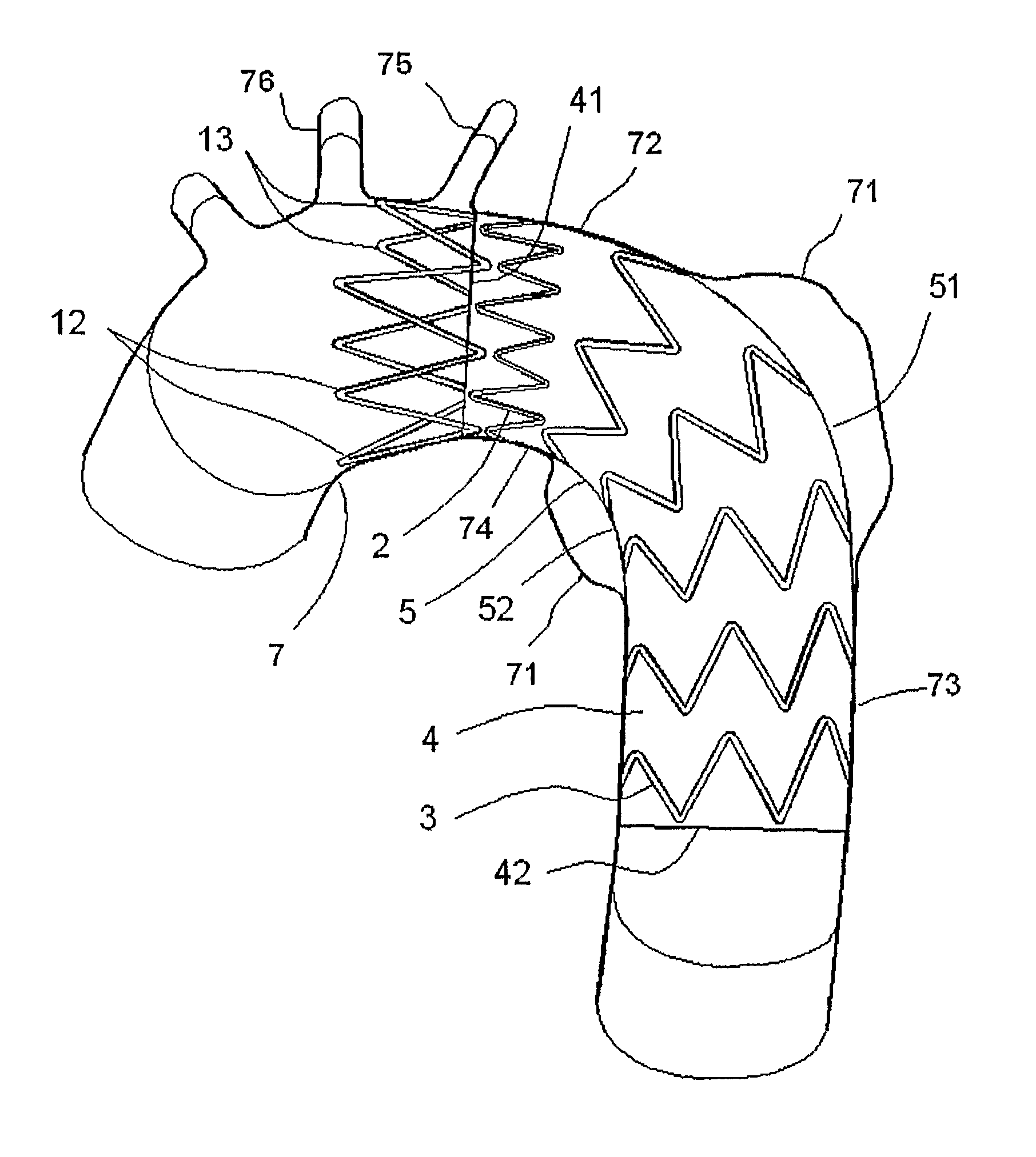
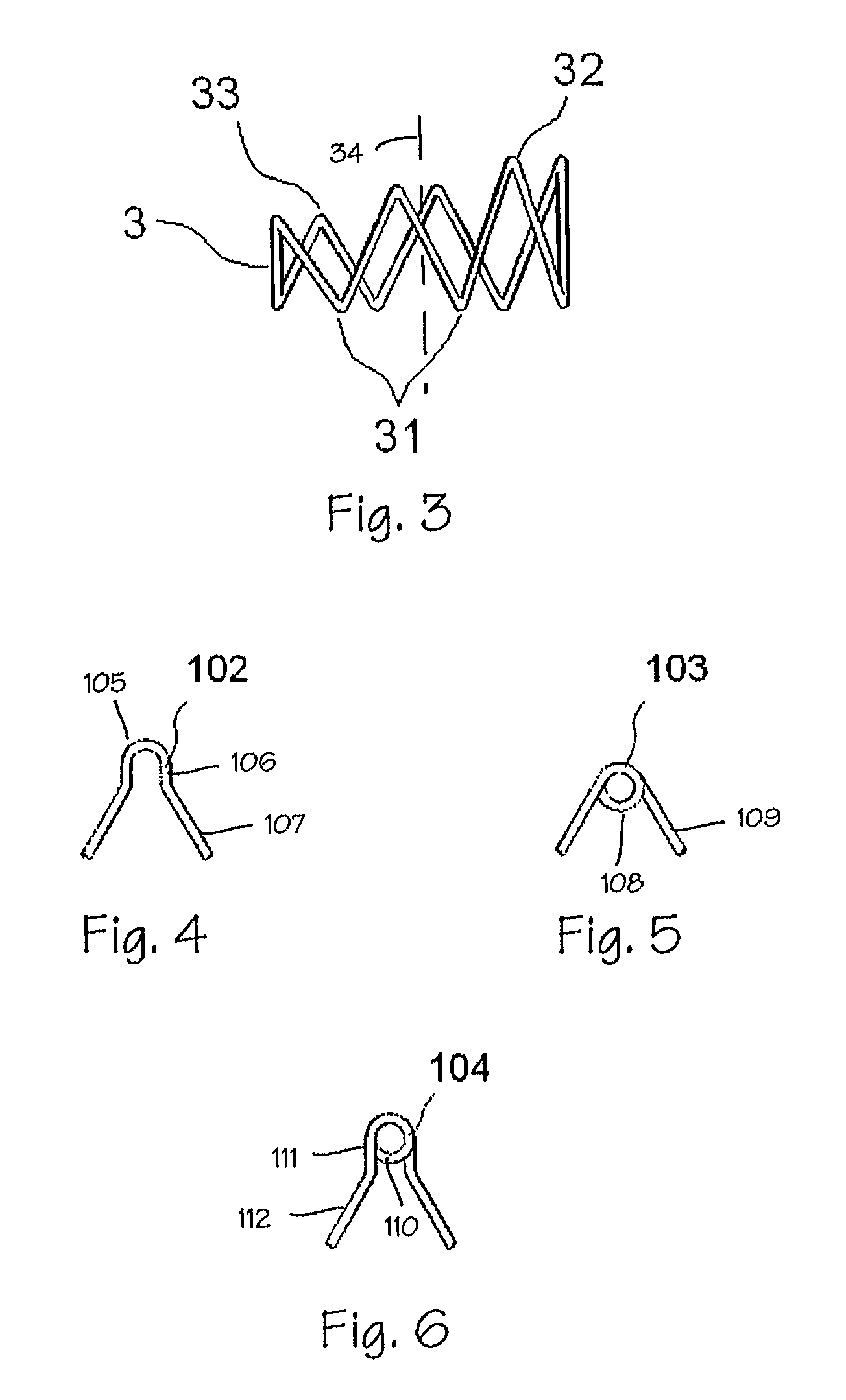
The present invention relates to an improved tubular stent graft and a bifurcated stent graft. The tubular stent graft has multiple sloping stent members, a mini-wave stent member, an open stent member and a tubular graft member, which provides improved flexibility, enhanced fixation to the vessel wall, reduced endoleakage and reduced potential of overturns of the proximal apexes of the open stent member during stent graft deployment. The bifurcated stent graft has a trunk graft portion with two branch portions extending from its distal end, which provides improved flexibility in a long branch portion, enhanced fixation to the vessel wall, reduced endoleakage and ease of introducing a guiding wire into a short branch graft portion. The bifurcated tubular graft member has a trunk graft portion with two branch portions extending from its distal end, which provides improved flexibility in a long branch portion, enhanced fixation to the vessel wall, reduced endoleakage and ease of introducing a guiding wire into a short branch graft portion.

Problems solved by technology

Blood pressure within the diseased portion of the blood vessel can cause the aneurysm to rupture and hemorrhage.
However, because conditions of weakened and diseased blood vessels differ greatly from patient to patient, existing stent-grafts have many drawbacks and may be restricted in their usefulness and applicability to certain procedures.
If the stent graft is not flexible, it cannot attach conformably to the wall of the blood vessel and may potentially kink.
A kink in the stent graft will not only weaken the fixation of the stent graft to the vessel wall, but it may also raise the blood pressure within the graft due to the uneven or smaller inner diameter of the graft.
High blood pressure in deployed stent grafts can lead to a higher flushing force of blood flow on the stent graft and a rise of the risk of stent graft migration as well.
If the stent graft migrates within the arotic arch, it not only fails to isolate the blood from the aneurysm, but also may cover other branch vessels extending from the aorta.
Covering the branch vessels in the aortic arch can lead to reduced blood flow to the rest of the body causing damage to nerves as well as vital organs of the patient and even death.
Similar problems also exist when using bifurcated stent grafts in treatment of abdominal aortic aneurysms for the iliac arteries which also contain a sharp curve.
The drawbacks in current stent graft designs also contribute to other complications in patients during and after stent graft treatment and placement.
When endoleakage occurs, the aneurysm is not fully isolated from blood flow within the patient's blood vessel and risk of a potentially fatal rupture of the aneurysm remains.
While stent grafts with open stents have many advantages, use and placement of stent grafts having open stents is not without its risks.
A stent graft deformed in this manner increases the risk of proximal endoleakage as well as increases the risk of vessel rupture due to sticking of overturned apexes into the vessel wall.
Longer stents, however, not only cover the intended branch vessel, but also risk covering one more branch vessels not intended to be covered.
Because stents are foreign objects within the human body, there is potential for the formation of blood clots known as thrombus on the surface of the stent wire.
Since thrombus formation is unstable, there is a risk for it to be flushed away from the stent.
Occlusion of branch vessels can potentially be fatal to the patient.
Less severe complications of open stents covering the port of the branch vessel include increased difficulty in future performance of minimally invasive surgery within the branch vessel due to vessel obstruction.
Other blood flow complications can occur during the deployment of bifurcated stents within patients.
The procedure placing the guiding wire into the contralateral iliac branch is difficult.

Method used


Image

  • Flexible stent-graft
  • Flexible stent-graft
  • Flexible stent-graft

Examples


Embodiment Construction

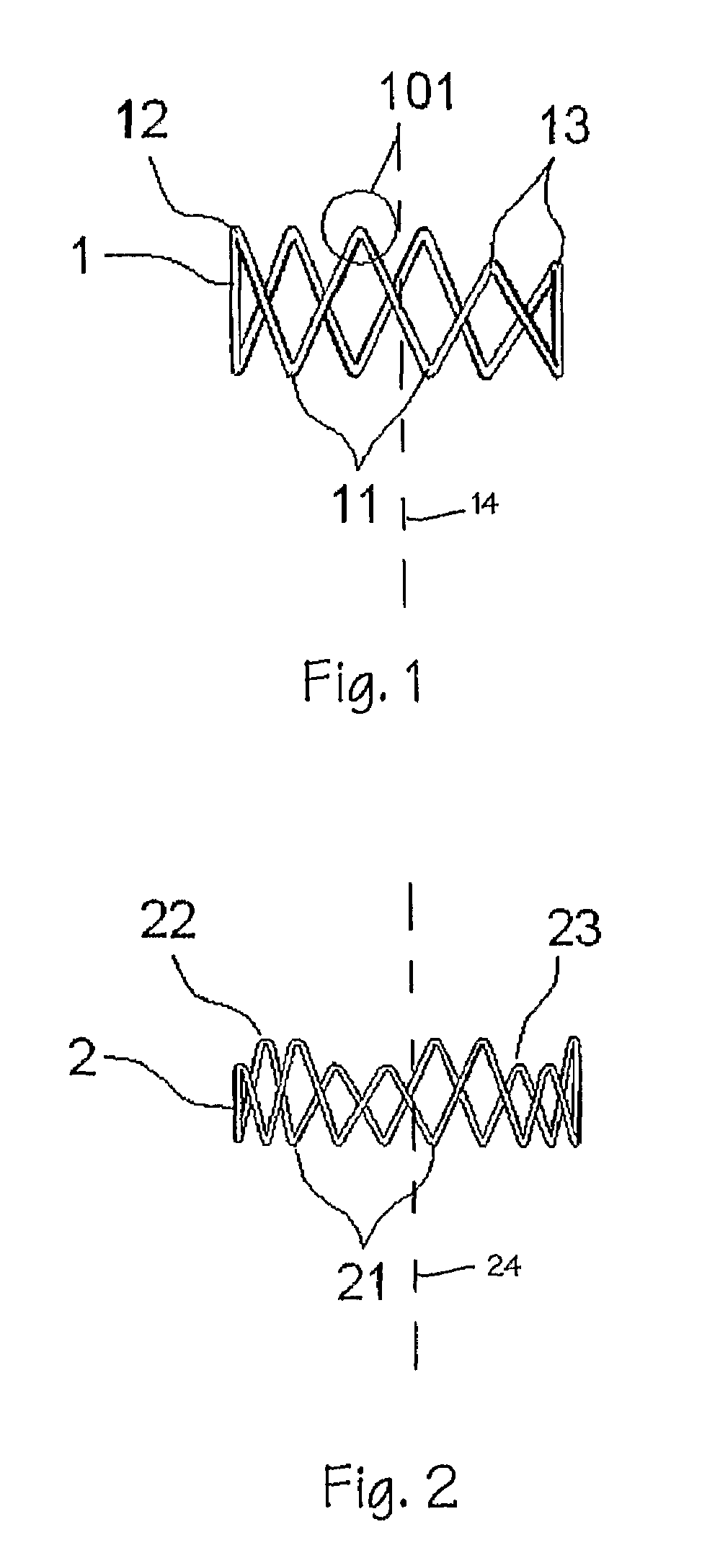
[0035]FIG. 1 illustrates an open stent member 1 formed from a single continuous wire and comprising multiple uneven undulations or sine waveforms of differing heights characterized by apexes or crests and troughs. The wire is formed in a tubular or ring-like configuration about a longitudinal axis. Apexes 11, 12, 13 characterize the tubular configuration. The distal apexes 11 or troughs of the open stent member 1 forming the distal circumference of the open stent lie on the same plane approximately horizontal / perpendicular to the longitudinal axis 14. The proximal apexes 12, 13 or crests are arranged along at least two different approximately horizontal / perpendicular to the longitudinal axis providing the undulations or waveforms with two or more different heights. The proximal apexes of the waveforms with the highest wave heights or of the undulations with the longest longitudinal lengths from the proximal apexes to the distal apexes are referred to as the high wave apexes 12 and t...


PUM


Abstract

A stent graft (5) comprises a tubular graft member (4), and a plurality of sloping stent members (3) substantially coaxial with and coupled to the tubular graft member (4). Each of the sloping stent members (3) comprises multiple uneven apexes characterizing a round tubular configuration with a distal end and a proximal end disposed about a longitudinal axis. The distal apexes of the sloping stent member (3) are arranged in substantially the same plane substantially horizontal to the longitudinal axis of the sloping stent member and the proximal apexes are arranged in a sloping plane oblique to the longitudinal axis.

Description

FIELD OF THE INVENTION[0001]The inventions described below relate the field of medical devices for use in treatment of vascular diseases. More specifically, the inventions described below relate to stent grafts for use in the treatment of thoracic aortic aneurysms and bifurcated stent grafts for use in treatment of abdominal aortic aneurysms.BACKGROUND OF THE INVENTIONS[0002]A stent graft is a medical device comprising a tube graft material supported by a metallic wire frame that may be used in the treatment of vascular diseases including aneurysms. Blood pressure within the diseased portion of the blood vessel can cause the aneurysm to rupture and hemorrhage. Stent-grafts can be used in the treatment of aneurysms, including thoracic aortic aneurysms and abdominal aortic aneurysms, by isolating the blood from the aneurysms. Typically, stents are deployed by placing them in a sheath of a delivery system and delivering the stent to the location where the aneurysm lies. After being dep...

Claims


Application Information

Patent Timeline
Patent Type & Authority Patents(United States)
IPC IPC(8): A61F2/06A61F2/07A61F2/82A61F2/89
CPCA61F2/07A61F2002/067A61F2002/075A61F2250/0039A61F2/89A61F2230/0067
Inventor LUO, QIYINIE, HONGLINZHU, QINGSHENG, WEIWENZHAO, FENGLIANGHE, HUILI, JIEGAO, YAN-BIN
Owner SHANGHAI MICROPORT ENDOVASCULAR MEDTECH (GRP) CO LTD
Learn More