Monitoring module for monitoring a process with an electric arc

a technology of monitoring module and process, which is applied in the direction of electrical apparatus construction details, color television, television systems, etc., can solve the problems of increasing space requirement, increasing the cost of service, and difficult to meet the needs of customers, so as to reduce the power of light sources, improve the effect of production efficiency and good accessibility

Inactive Publication Date: 2015-06-16
FRONIUS INTERNATIONAL GMBH
View PDF52 Cites 19 Cited by
  • Summary
  • Abstract
  • Description
  • Claims
  • Application Information

AI Technical Summary

Benefits of technology

[0055]It is beneficial if the monitoring module according to the invention is mounted at a torch for performing a process with an electric arc (with the electric arc being protected in particular by a protective gas from a gas nozzle). The advantage of the monitoring module according to the invention come out especially here, because the electric arc glows extremely brightly and an image capturing without a flash lamp would only show the very next environment of the electric arc. Nevertheless, the device according to the invention is also applicable for other machining methods with an electric arc, for example for the welding, soldering, cutting, cleaning. Laser welding, laser-hybrid-welding, plasma processes and others. This means that the monitoring module can be used for various applications, because its image capturing is essentially independent from the ambient light. Advantageously, the monitoring module is mounted to a fixed point relatively to the gas nozzle, with the result that the latter represents a fixed point of reference. Other advantages can be taken from the descriptions above.
[0056]It is also advantageous if the torch comprises a gas nozzle and the monitoring module is arranged at the torch in such a way that the gas nozzle at least partially covers an electric during the image capturing, seen in the direction of the optical axis of the camera. In this way, the adverse influence of the electric arc disturbing the quality of the image can be eliminated, at least partially, if not entirely.
[0057]Advantageously, the monitoring module is mounted at the torch at a distance of approximately 20 to 30 cm from the electric arc or the ending of the wire. Due to the relatively large distance, the tube bend of the torch can be kept freely accessible, which does not have a negative effect on the exchange of the bearing parts, such as gas nozzle or contact tube. Thus, a good accessibility for the respective applications is maintained. Furthermore, a splash protection as well as a radiation protection is provided. Due to the radiation protection, the power of the light source can be reduced, too, if necessary.
[0058]According to the invention, advantageously a covering for the at least one opening of a monitoring module is provided, with the covering being made of a circular frontpane with a concentric, cylindrical fixing surface and the cylindrical fixing surface having a smaller diameter than the frontpane and an air outlet or at least one deflection device, which is provided for orientating the discharging air beam Perpendicular to the optical axis of a camera of a monitoring module, being integrated in the frontpane. This form of covering is, on the one hand, easy to produce, and on the other hand, easy to mount. Due to the integration of an air outlet, it serves a double purpose additionally.
[0059]It is thereby advantageous if the at least one deflection device is arranged outside of an annular ring of the frontpane. In this way, the exiting air flow can be aligned perpendicular to the optical axis of the camera and / or the light source, or essentially parallel to the outer surface of the covering. In this way, the outer surface can be protected against impurities in an optimal manner.
[0060]It is finally advantageous if at least one fixing device is arranged at least at the barrel of the cylindrical fixing surface. In this way, the covering can be fixed at the housing with the result that it cannot drop out accidentally.

Problems solved by technology

The disadvantage of the known method is that they are proprietary that means designed for the respective type of machine and the respective purpose of application.
Additionally, the solutions are comparably expensive and difficult to service due to their low number of units.
Also the restricted accessibility, the increased space requirement and the security against the increased impact of dirt of the process such as smoke or splashes that needs improvement are disadvantageous.
For this reason, also the maintenance effort increases.

Method used


Image

  • Monitoring module for monitoring a process with an electric arc
  • Monitoring module for monitoring a process with an electric arc
  • Monitoring module for monitoring a process with an electric arc

Examples


Embodiment Construction

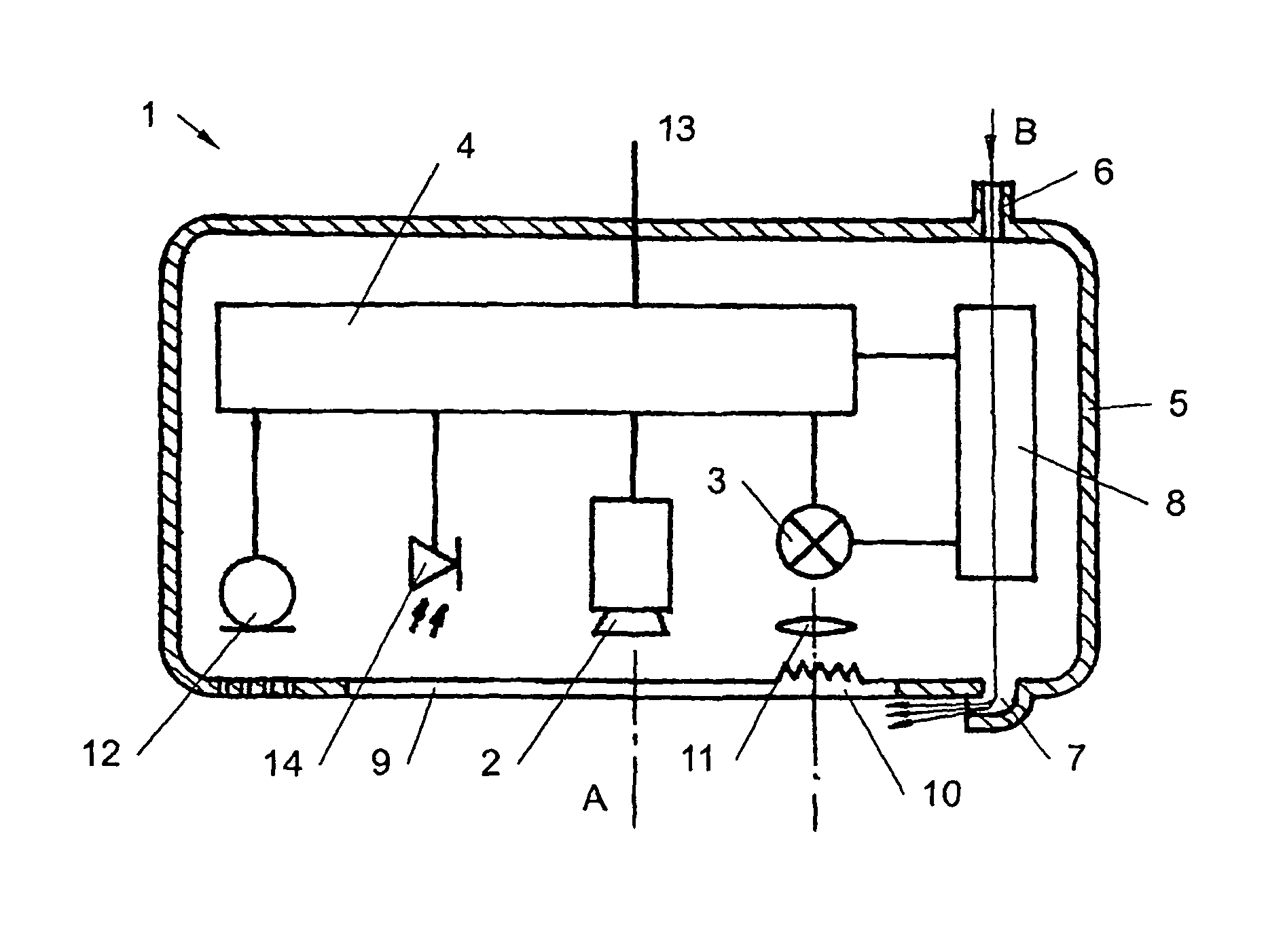
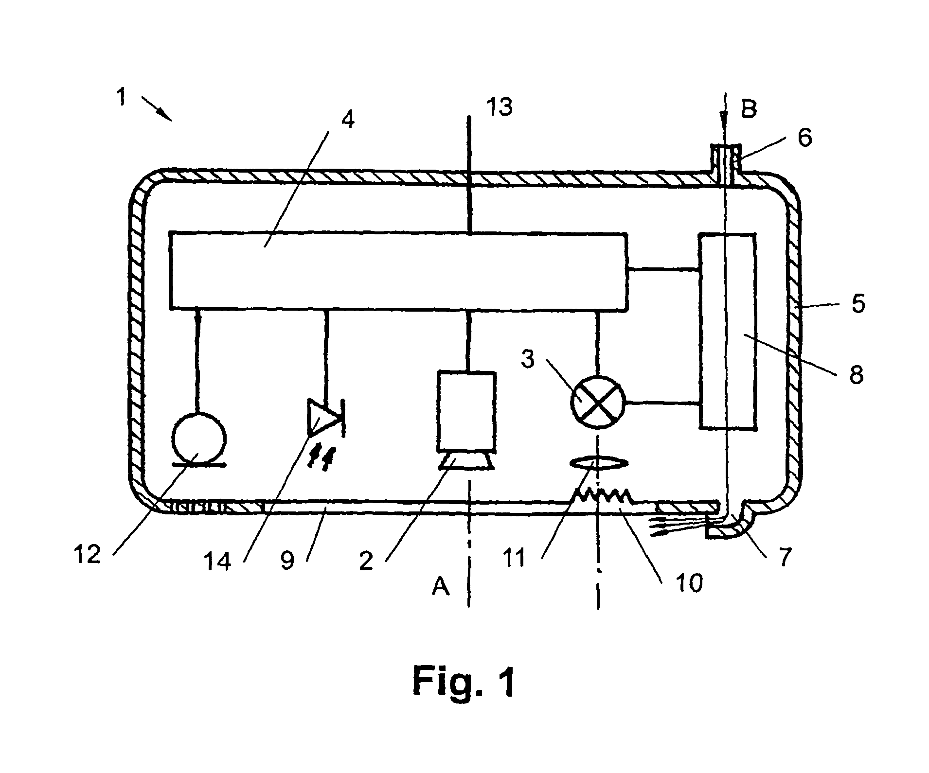
[0070]It must first be stated that in the various embodiments described, identical parts have been marked with the same reference identifiers and the same parts descriptions. It is therefore possible to transfer the disclosures contained in the overall description to the identical parts with the same reference identifiers or the same parts descriptions. The selected positioning terms are used in the description, such as top, bottom, side etc., which refer directly to the described and the depicted figures and which can be correspondingly transferred to the new position in the event of a change in position. Furthermore, individual characteristics or combinations of characteristics from the various embodiments shown and described can present independent or inventive solutions, or solutions according to the present invention.

[0071]The exemplary embodiments refer to possible variants of embodiment of the monitoring module according to the invention are not intended to limit the scope of...


PUM

PropertyMeasurementUnit
wavelengthaaaaaaaaaa
distanceaaaaaaaaaa

Abstract

A monitoring module for monitoring an electric arc machining process includes a camera, a photo flash lamp and a control system that controls the photo flash lamp in such a way that it illuminates when the camera records the image. The components are arranged in a common housing. The common housing includes a compressed air connection and an air outlet (7) or a deflection device arranged at the housing, which is provided for the orientation of the discharging air beam across the optical axis of the camera. Furthermore, an air flow caused by the compressed air is led via the light source and/or the control system and/or a charging connection for the light source.

Description

CROSS REFERENCE TO RELATED APPLICATIONS[0001]This application is the National Stage of PCT / AT2010 / 000330 filed on Sep. 13, 2010 which claims priority under 35 U.S.C. §119 of Austrian Application No. A 1448 / 2009 filed on Sep. 11, 2009, the disclosure of which is incorporated by reference. The international application under PCT article 21(2) was not published in English.BACKGROUND OF THE INVENTION[0002]1. Field of the Invention[0003]The invention relates to a monitoring module for monitoring a process with an electric arc, with the electric arc being led with a torch, comprising a camera, a photo flash lamp and a control system that controls the photo flash lamp in such a way that it illuminates when the camera records an image and the said components (camera, photo flash lamp, control system) are arranged in a common housing.[0004]2. The Prior Art[0005]For some time now, processes with an electric arc, such as e.g. welding processes, have been monitored in order to be able to recogn...

Claims


Application Information

Patent Timeline
Patent Type & Authority Patents(United States)
IPC IPC(8): H05K5/03B23K9/095
CPCB23K9/0956
Inventor HOERTENHUBER, MARTINREINTHALER, GUENTHER
Owner FRONIUS INTERNATIONAL GMBH
Why Eureka
Try Eureka