
Cooling device and electronic device

a technology of electronic devices and cooling devices, which is applied in the direction of lighting and heating apparatus, instruments, and modifications by conduction heat transfer, can solve the problems of inadequate thermal diffusion, insufficient height reduction of mounting area, and inability to reduce mounting area, etc., and achieve the effect of efficient conductivity of heat to the bas

Inactive Publication Date: 2015-06-16
MOLEX INC
View PDF5 Cites 0 Cited by
  • Summary
  • Abstract
  • Description
  • Claims
  • Application Information

AI Technical Summary

Benefits of technology

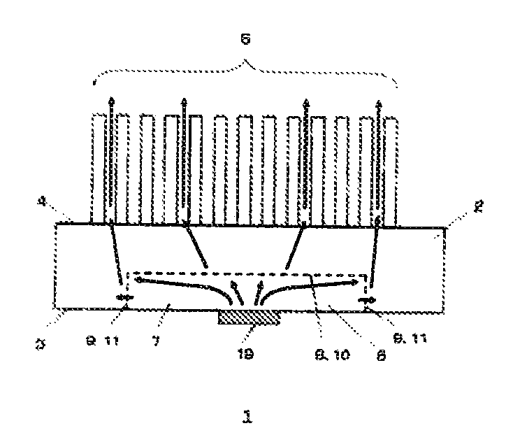
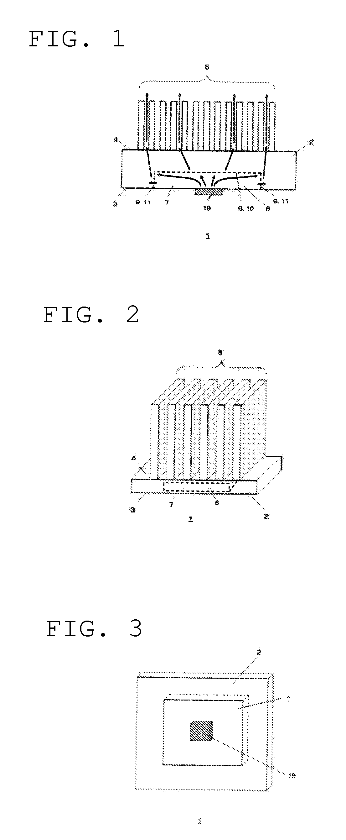
The present application provides a small cooling device for efficiently cooling a heat-generating element that produces a lot of heat while keeping the mounting area low. The device has a base with a recessed part and heat-radiating fins that have the same thickness as the base without the recessed part and the fins. This design ensures even distribution of heat over the entire base and fins, which helps to improve cooling efficiency.

Problems solved by technology

While the disclosure in the '170 Application can reduce the mounting area heightwise, (1) the diffusion of heat conducted in sequential order from the heat generating element, the heat pipe and the heat sink is insufficient, (2) thermal diffusion is inadequate because the role sharing between the heat pipe and the heat sink is unclear, (3) the mounting area cannot be reduced in the planar direction because of insufficient thermal diffusion, and (4) the mounting area reduction heightwise is less than adequate in actuality because of an inadequate heat exhaust design.
Because the mounting area reduction is inadequate in the planar direction, there is a significant size discrepancy with respect to the heat generating element and this has an adverse effect on the overall mounting design for the electronic device.
Because the heat pipe characteristics and the heat sink characteristics cannot be optimized, the overall heat exhaust performance is deficient.

Method used


Image

  • Cooling device and electronic device
  • Cooling device and electronic device
  • Cooling device and electronic device

Examples


Embodiment Construction

[0053]While the Present Application may be susceptible to embodiment in different forms, there is shown in the Figures, and will be described herein in detail, specific embodiments, with the understanding that the disclosure is to be considered an exemplification of the principles of the Present Application, and is not intended to limit the Present Application to that as illustrated.

[0054]In the illustrated embodiments, directional representations—i.e., up, down, left, right, front, rear and the like, used for explaining the structure and movement of the various elements of the Present Application, are relative. These representations are appropriate when the elements are in the position shown in the Figures. If the description of the position of the elements changes, however, it is assumed that these representations are to be changed accordingly.

[0055]For purposes of the Present Application, a “heat pipe” can be any member, component, element or device able to cool a heat generating...


PUM


Abstract

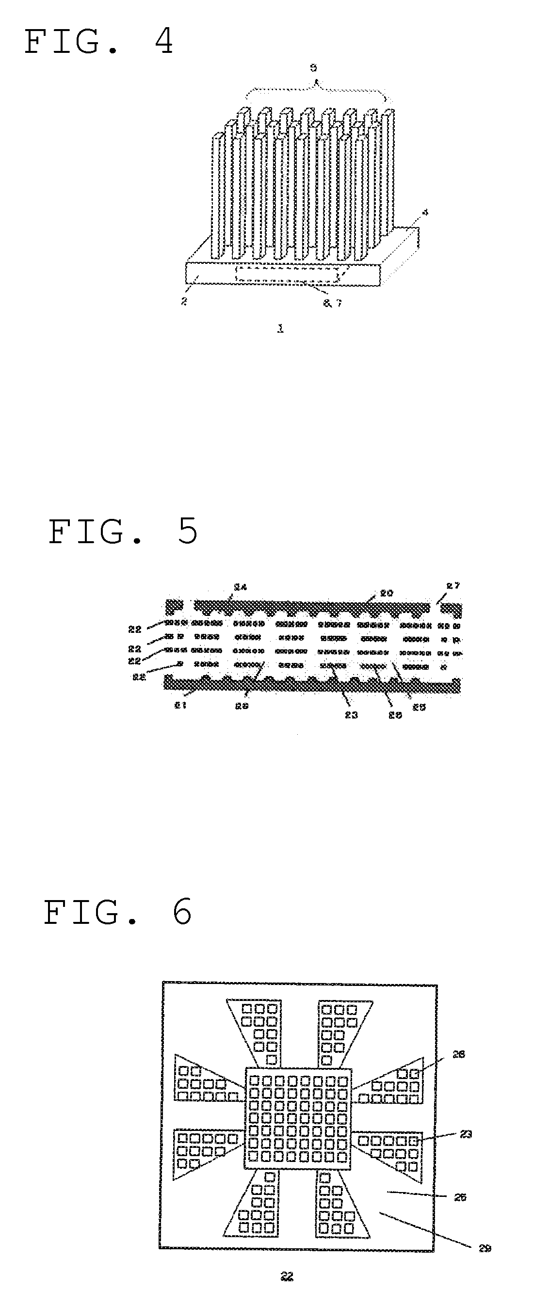
The cooling device comprises a base with a recessed part in a first surface, a plurality of heat radiating fins standing erect on a second surface on the reverse side of the first surface, and a flat, plate-like thermal diffusion part housed inside the recessed part. The upper surface of the thermal diffusion part makes thermal contact with the upper surface of the recessed part, the side surface of the thermal diffusion part makes thermal contact with the side surface of the recessed part, and the thermal diffusion part diffuses in the planar and orthogonal directions heat from the heat generating element arranged on the bottom surface of the thermal diffusion part by vaporizing and condensing coolant sealed inside.

Description

REFERENCE TO RELATED APPLICATIONS[0001]The Present Application claims priority to prior-filed Japanese Application No. 2009-282318, entitled “Cooling Device, Electronic Device,” and filed 12 Dec. 2009, the contents of which is fully incorporated in its entirety herein.BACKGROUND OF THE PRESENT APPLICATION[0002]The Present Application relates to a cooling device for diffusing heat from a heat generating element such as an electronic component and radiating the diffused heat to the outside, and the Present Application relates more specifically to a small cooling device with a superior thermal design.[0003]Electronic devices, industrial equipment and automobiles all use elements and electronic components such as semiconductor integrated circuits, LED elements and power devices that generate a lot of heat. When the heat generated by these elements and electronic components is above a given temperature, the operation of these elements and components cannot be ensured and the heat has an ...

Claims


Application Information

Patent Timeline
Patent Type & Authority Patents(United States)
IPC IPC(8): H05K7/20H01L23/367H01L23/427F28D15/02F28F3/02G06F1/20
CPCF28F3/02G06F1/20G06F1/203H01L23/367H01L23/427F28F3/022F28D15/0233H05K7/2039H01L2924/0002H01L2924/00
Inventor NAGASAWA, HIDEO
Owner MOLEX INC
Learn More