Image forming apparatus

a technology of image forming apparatus and blank portion, which is applied in the direction of electrographic process apparatus, instruments, optics, etc., can solve the problems of increasing fogging in blank portion, and achieve the effect of stabilizing image density and suppressing fogging

Active Publication Date: 2015-06-16
CANON KK
View PDF5 Cites 9 Cited by
  • Summary
  • Abstract
  • Description
  • Claims
  • Application Information

AI Technical Summary

Benefits of technology

[0008]The present invention is directed to further advancement of the foregoing conventional technique. In particular, the present invention is directed to an image forming apparatus including a developing device in which a developer bearing member and a supply member rotate in opposite directions, wherein an image forming speed can be changed while stabilizing image density and suppressing fogging.

Problems solved by technology

In such a case, fogging has been identified to increase in blank portions as the printing speed decreases.

Method used


Image

  • Image forming apparatus
  • Image forming apparatus
  • Image forming apparatus

Examples


Embodiment Construction

[0019]Various exemplary embodiments, features, and aspects of the invention will be described in detail below with reference to the drawings.

[0020]Sizes, materials, shapes, and relative arrangement of components described in the exemplary embodiments of the present invention may be modified as appropriate according to configuration and various conditions of apparatuses to which the exemplary embodiments of the present invention are applied. The scope of the present invention is not intended to be limited to the following exemplary embodiments.

[0021]An exemplary embodiment of the present invention will be described with reference to FIGS. 1 to 5.

[0022]Image Forming Apparatus

[0023]An overall configuration of an electrophotographic image forming apparatus (image forming apparatus) according to the present exemplary embodiment will initially be described.

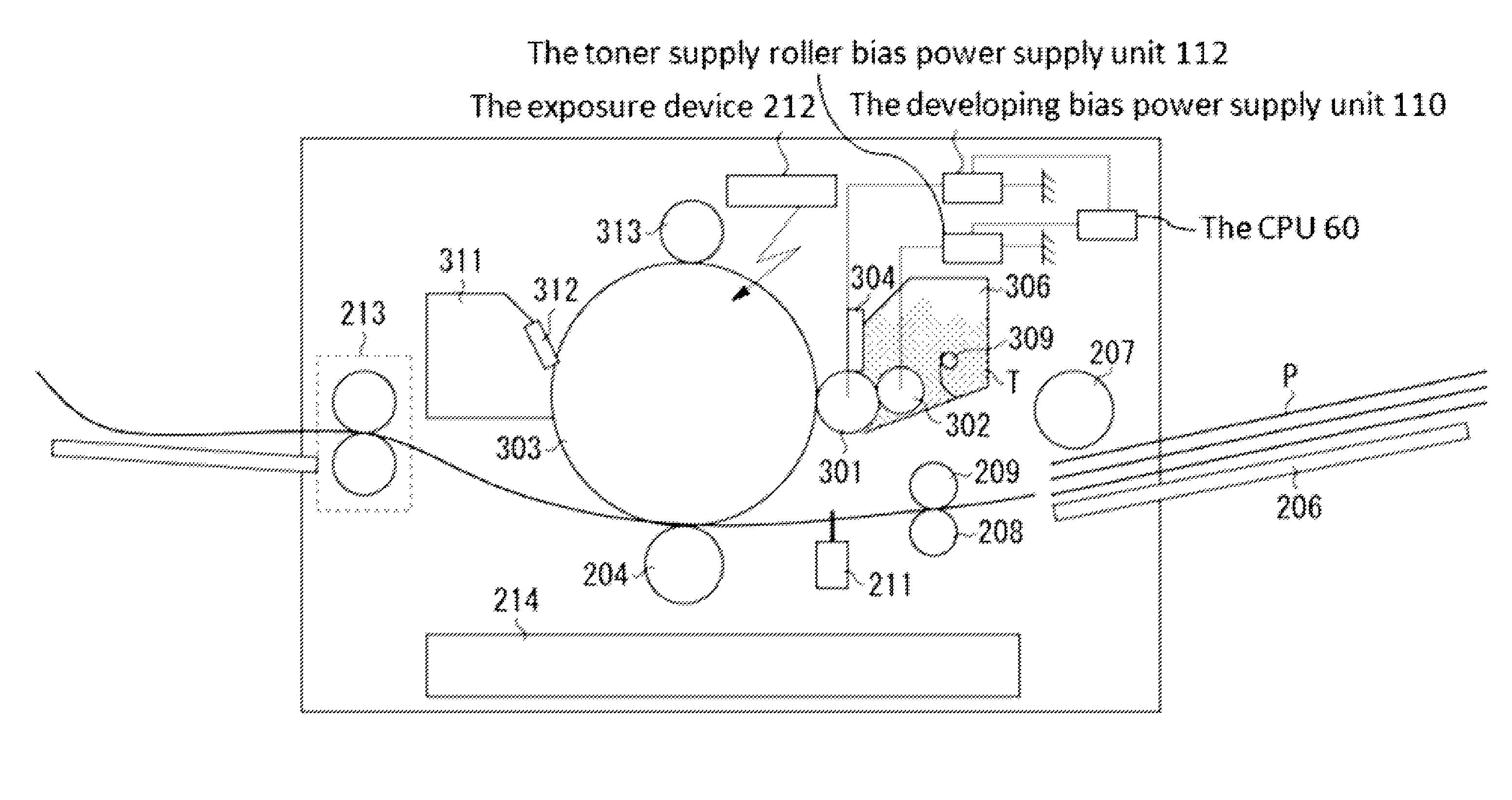
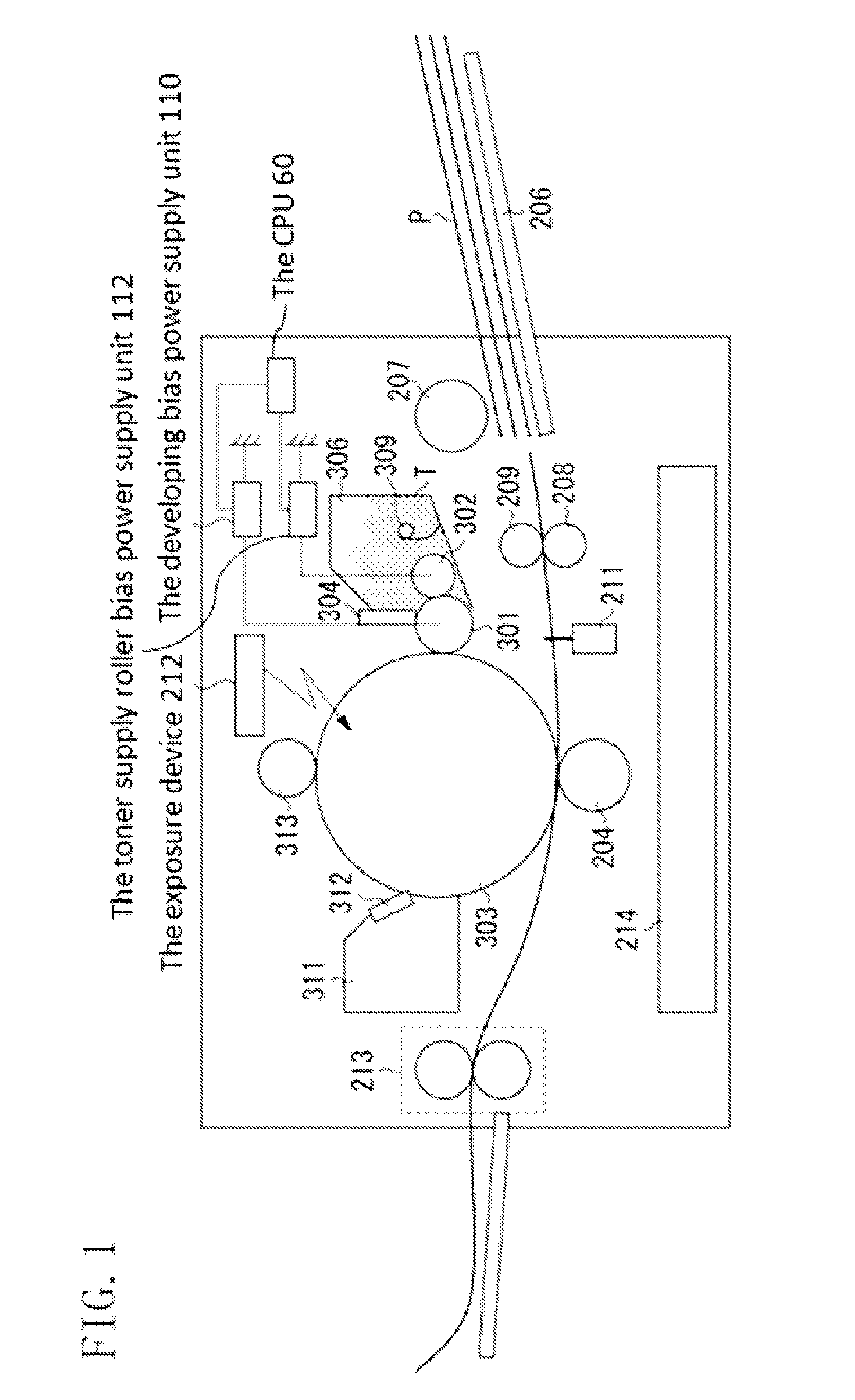
[0024]FIG. 1 is a schematic cross-sectional view illustrating a configuration of the image forming apparatus according to the present ...


PUM


Abstract

An image forming apparatus includes a control unit controlling first and second voltage application mechanisms and shifting a difference Vdif (=Vrs−Vdr) between Vrs and Vdr toward polarity opposite to normal charge polarity of a developer as S decreases, where S is an absolute value of a speed difference between a circumferential speed of an image bearing member, which rotates while bearing an electrostatic latent image and a circumferential speed of a developer bearing member, which rotates at a constant circumferential speed ratio with respect to the image bearing member to develop the electrostatic latent image while bearing the developer, Vdr is a voltage that the first voltage application mechanism applies to the developer bearing member, and Vrs is a voltage that the second voltage application mechanism applies to the developer supply member.

Description

BACKGROUND OF THE INVENTION[0001]1. Field of the Invention[0002]The present invention relates to an image forming apparatus which forms an image on a recording material by using an electrophotographic method.[0003]2. Description of the Related Art[0004]An image forming apparatus using an electrophotographic image forming method (electrophotographic process), such as a printer, uniformly charges an electrophotographic photosensitive member (hereinafter, referred to as a “photosensitive member”) serving as an image bearing member and selectively exposes the charged photosensitive member to form an electrostatic image on the photosensitive member. A developing device visualizes the electrostatic image formed on the photosensitive member into a toner image by using a developer (also referred to as toner). The toner image formed on the photosensitive member is transferred to a recording material such as a recording sheet and a plastic sheet. Heat and pressure are further applied to the t...

Claims


Application Information

Patent Timeline
Patent Type & Authority Patents(United States)
IPC IPC(8): G03G15/06G03G15/08
CPCG03G15/065G03G15/0806G03G15/0808
Inventor YOSHIDA, NOBUYOSHIMITSUI, YOSHIHIROHAYASHI, KODAITANIGUCHI, HISASHI
Owner CANON KK
Why Eureka
Try Eureka