Insulation system for a stator bar with low partial discharge

Inactive Publication Date: 2015-06-16
RAO DANTAM K
View PDF47 Cites 8 Cited by
  • Summary
  • Abstract
  • Description
  • Claims
  • Application Information

AI Technical Summary

Benefits of technology

[0015]The disclosed insulation system reduces partial discharges at almost all areas within the insulation. Such insulation system will simplify the manufacturing process as it avoids the need to wind four different types of insulation tapes as used i

Problems solved by technology

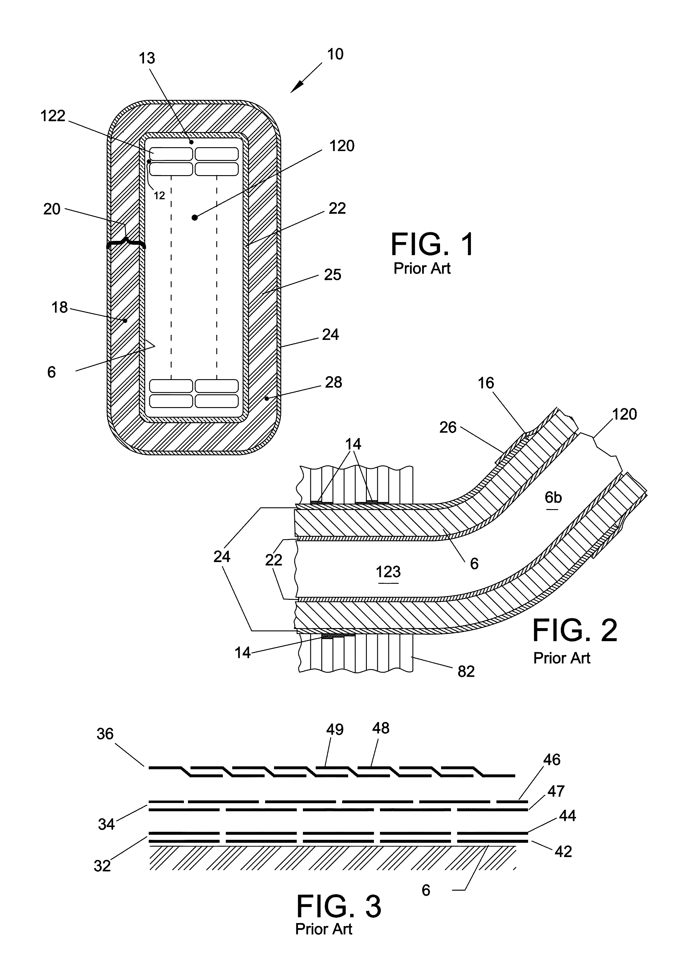
Partial discharges (aka corona or void discharge) are caused by electric fields (aka electric stress) that are beyond the dielectric strength of air, so cause ionization currents, which literally burn the insulation locally and degrade its life.
A mismatch between ECP and SGL caused by such wide variation in resistance often results in a visible discoloration around the overlapping edge 16, a defect known as “white band” in the tr

Method used


Image

  • Insulation system for a stator bar with low partial discharge
  • Insulation system for a stator bar with low partial discharge
  • Insulation system for a stator bar with low partial discharge

Examples


Example

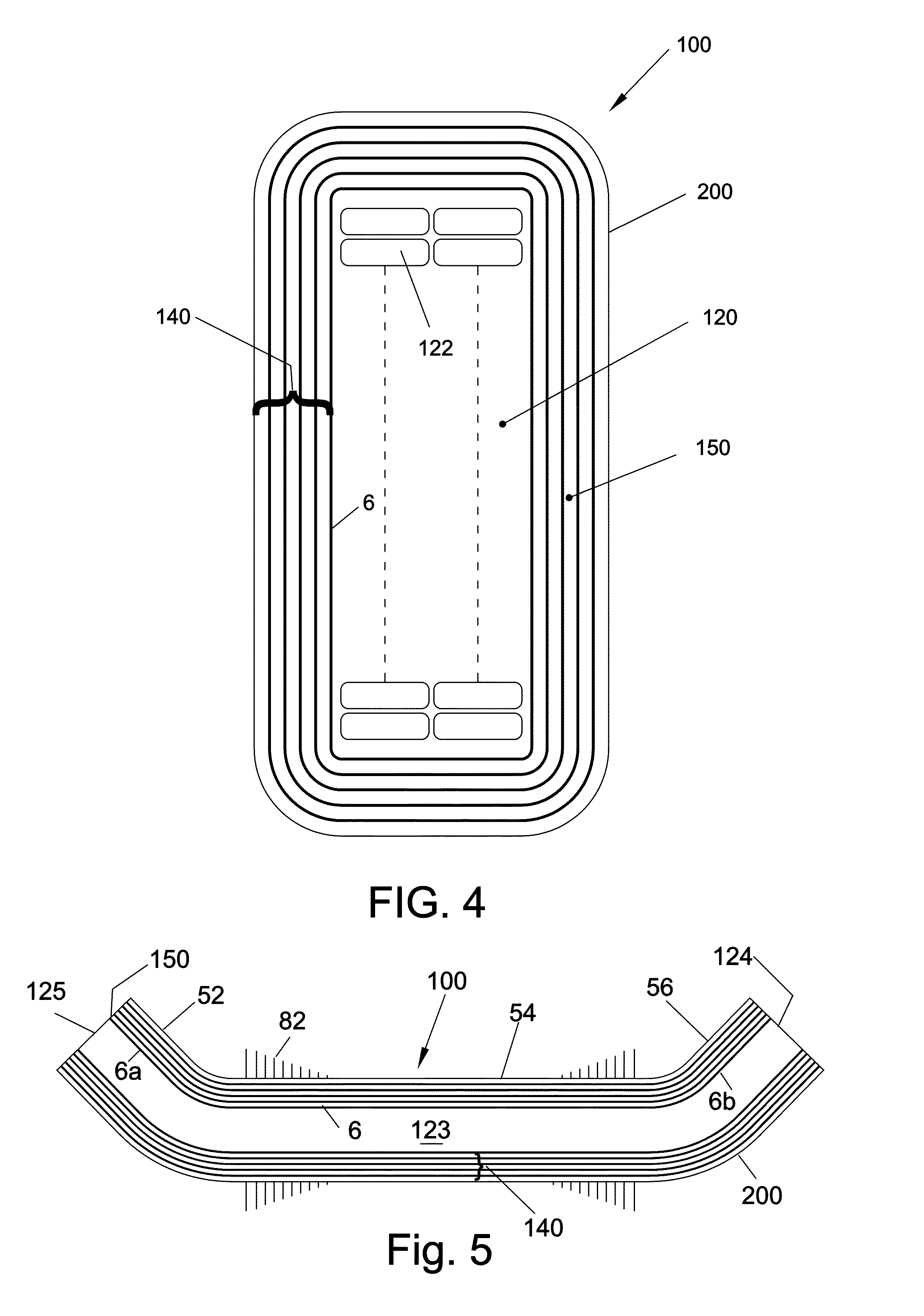
[0042]FIG. 9 shows cross-section of a first embodiment 150 of the anti-corona tape. This tape insulates against high voltage and protects the insulation system 200 against discharges in voids anywhere. It comprises a first insulative sublayer 160 engaged to a second resistive sublayer 170 at the interface 166. One uses known manufacturing steps that ensure that both sublayers are free of voids. The insulative sublayer 160 insulates against high voltage. The resistive sublayer 170 on the other hand protects against void discharges using following operating mechanism. If there are ten resistive sublayers, the potential gradient between successive sublayers is one-tenth of the main voltage. The air voids in any resin between successive layers are thus subjected to substantially smaller fraction of the rated voltage. This greatly reduces the void discharges. Note that such air voids are surrounded by resistive sublayers. The resistance across these layers is lower than that across air v...


PUM


Abstract

The invention discloses an insulation system for a stator bar in high voltage electric machines, comprising an anti-corona tape that is wound uniformly and continuously over the entire length of a bare bar. The anti-corona tape comprises a thin resistive sublayer engaged to a thick insulative sublayer. The insulative sublayer provides resistance against high voltage. The resistive sublayer protects the insulation against partial discharges. These partial discharges can occur in voids, such as delamination voids, transposition crossover gaps, strand corners, slot voids, overlap voids etc. The resistive sublayer also increases the thermal conductivity hence reduces the operating temperature. Such insulation using a single-tape approach can replace several layers used in prior-art, viz., an internal corona protection layer, an external corona protection layer, a stress-grading layer and mica layers. This single-tape approach also simplifies the process of manufacturing the stator bar and reduces its cost.

Description

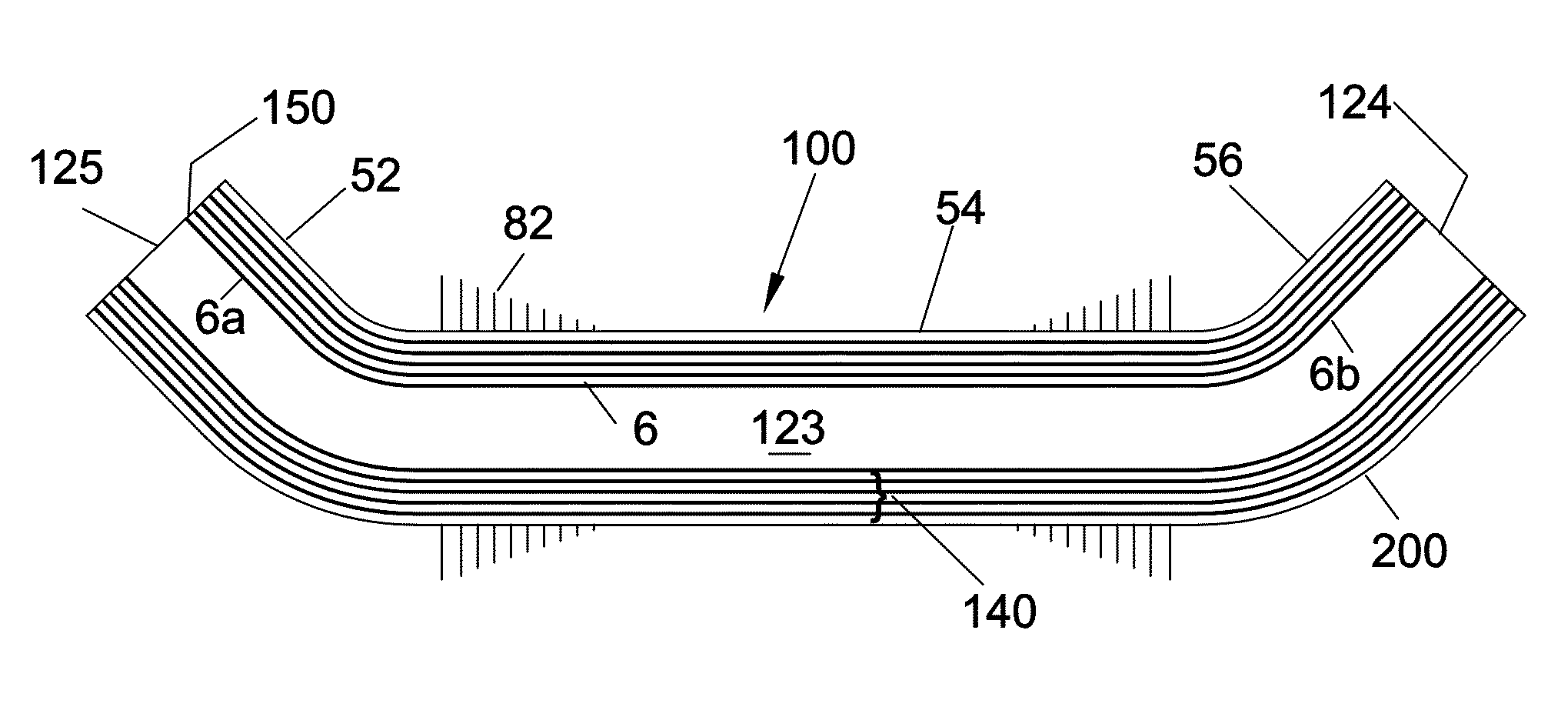
BACKGROUND[0001]The present disclosure relates generally to a stator bar in a high voltage electric machine, particularly to the insulation system therein.[0002]FIG. 1 shows cross-section of a stator bar 10 in a high voltage electric machine. It comprises a bare bar 120 and a prior-art insulation system 20 over its periphery 6. The bare bar 120 is made of two or more columns of transposed conductive strands 122, with empty spaces filled with fillers to form a rectangular section having four rounded corners. As shown in FIG. 2 and FIG. 5, the bare bar has a central straight part 123 that sits inside a slot of iron lamination core 82 and two bent-arms 6a, 6b that protrude out of the slot. All insulation systems follow this profile of the bare bar 120.[0003]This insulation system 20 provides insulation against high voltage and simultaneously reduces partial discharges in some, but not all, air voids. Partial discharges (aka corona or void discharge) are caused by electric fields (aka e...

Claims


Application Information

Patent Timeline
IPC IPC(8): H02K21/00H02K23/26H02K27/02H02K3/40H02K3/30
CPCH02K3/40H02K3/30
Inventor RAO, DANTAM K.
Owner RAO DANTAM K
Why Eureka
Try Eureka