
Dry-type high-frequency transformer

A dry-type transformer and insulating layer technology, applied in the direction of fixed transformer or mutual inductance, transformer/inductor parts, transformer/inductor coil/winding/connection, etc. problems, to avoid gaps and cracks, small partial discharge, and ensure the effect of insulation performance

Active Publication Date: 2018-07-20
GLOBAL ENERGY INTERCONNECTION RES INST CO LTD +1
View PDF9 Cites 6 Cited by
  • Summary
  • Abstract
  • Description
  • Claims
  • Application Information

AI Technical Summary

Problems solved by technology

[0006] The purpose of the present invention is to overcome the problem in the prior art that the dry insulating structure composed only of epoxy resin cannot meet the long-term operation reliability requirements of high-frequency transformers, and to provide a new type of winding with an insulating structure

Method used


Image

  • Dry-type high-frequency transformer

Examples


Embodiment 1

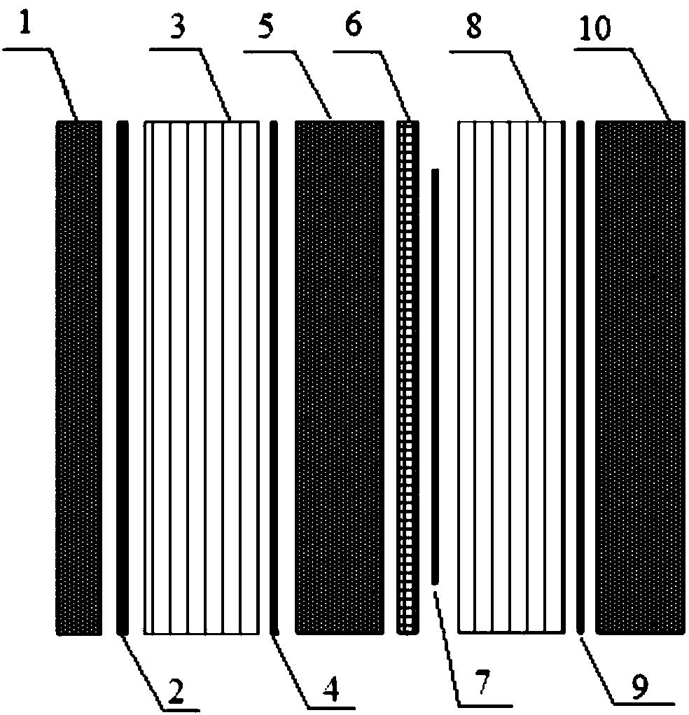
[0036] The winding with an insulation structure provided in this embodiment includes a first insulation layer, a transition layer one, a coil, a transition layer two, and a second insulation layer in sequence. The coil is made of ionic conductor material as a wire. The turns of the coil are separated by insulating materials. DMD insulating composite material can be selected. The first insulating layer and the second insulating layer are made of cast epoxy resin. The transition layer is one And the second transition layer is made of silicone rubber sheet.

[0037] By providing a transition layer between the coil and the insulating layer, it can play a buffering role, reduce the phenomenon of air gaps and cracks at the interface between the insulating layer and the coil, avoid creeping discharge, thereby improving the insulation performance and reducing the level of partial discharge. The insulating elastic material is a preferred transition layer material.

Embodiment 2

[0039] The winding with insulation structure provided in this embodiment is structurally the same as the winding with insulation structure provided in the embodiment. The difference is that the second transition layer of this embodiment is made of electrostatic shielding material semiconductor crepe paper. In this way, the second transition layer It can not only play a certain buffering effect, but also shield the electric field outside the coil, achieve the effect of uniform electric field, and further reduce the level of partial discharge, thereby preventing the occurrence of short-circuit breakdown.

Embodiment 3

[0041] The winding with an insulating structure provided in this embodiment includes a first insulating layer, a transition layer one, a coil, a transition layer two, and a second insulating layer in sequence. Among them, the first transition layer and the second transition layer are made of electrostatic shielding materials.

[0042] By selecting the electrostatic shielding material as the material of the transition layer 1 and the transition layer 2, the electric field inside and outside the coil can be well shielded, making this winding with an insulating structure more suitable for high-voltage windings and has better insulation performance. The partial discharge level is minimized to ensure that the winding with an insulating structure is safe and reliable during long-term operation.

[0043] In this embodiment, a semiconductor self-adhesive tape is used as an electrostatic shielding material, an elastic insulating material silicon rubber plate is used as a transition layer, a...


PUM


Abstract

The invention belongs to the technical field of a dry-type high-frequency transformer, and particularly relates to the dry-type high-frequency transformer which can be used for improving insulation performance and reducing local discharging quantity of the transformer and is provided with an insulation structure. By additionally arranging a transition layer having a buffer effect between the winding coil and the insulation layer, favorable linkage between the winding and the insulation layer is achieved, phenomena such as gap and crack between the insulation layer and the winding in the priorart are prevented, and the local discharging level can be effectively reduced; and moreover, an insulation elastic material and an electrostatic shielding material are preferably used as transition layers, a potential risk of large local discharging quantity of the insulation layer at a high-voltage side and a low-voltage side is prevented, the insulation performance of the dry-type high-frequencytransformer is greatly improved, the service lifetime of the dry-type high-frequency transformer is greatly prolonged, and the long-term running reliability of a power electronic transformer device is improved.

Description

Technical field [0001] The invention belongs to the technical field of dry-type transformers, and specifically relates to a winding with an insulating structure that can improve the insulation performance of a dry-type high-frequency transformer and reduce the partial discharge of the transformer. Background technique [0002] Power Electronic Transformer (PET) is a new type of transformer, which uses power electronic devices and power electronic conversion technology to convert and control energy. Compared with traditional transformers, power electronic transformers are smaller and lighter, and have the advantages of saving materials and energy. Power electronic transformers have broad application prospects in smart grids. They can not only provide flexible access solutions for microgrids, distributed energy and renewable energy; they can also ensure the power quality of the power system and fully satisfy the power users’ power supply reliability. , Safety, flexibility and econ...

Claims


Application Information

Patent Timeline
Patent Type & Authority Applications(China)
IPC IPC(8): H01F27/32H01F27/28H01F19/04
CPCH01F19/04H01F27/288H01F27/323H01F27/325
Inventor 邓占锋赵国亮乔光尧王东任西周康伟周哲徐云飞李卫国雷晰苏铁山石秋雨曾洪涛
Owner GLOBAL ENERGY INTERCONNECTION RES INST CO LTD
Learn More