
Irrigant distribution system for electrodes

a distribution system and electrode technology, applied in the field of irrigant distribution system for electrodes, can solve the problems of limited, corrals, local impedance rise, time-consuming process, etc., and achieve the effect of promoting dilution and movement of the blood pool surrounding

Active Publication Date: 2015-06-30
ST JUDE MEDICAL ATRIAL FIBRILLATION DIV
View PDF55 Cites 30 Cited by
  • Summary
  • Abstract
  • Description
  • Claims
  • Application Information

AI Technical Summary

Benefits of technology

The patent describes an improved ablation electrode assembly for use in catheters that can improve temperature correlation with tissue and prevent charring and coagulum formation. The assembly can also include a mechanism to irrigate the targeted areas with biocompatible fluids, such as saline solution, to enable deeper and greater volume lesions, and conform to cardiac anatomy for better energy delivery during RF ablation. Overall, the technical effects of the patent include improved ablation efficiency and reduced complications during the procedure.

Problems solved by technology

This lesion disrupts undesirable cardiac activation pathways and thereby limits, corrals, or prevents errant conduction signals that can form the basis for arrhythmias.
During RF ablation, local temperature elevation can result in coagulum formation on the ablation electrode, resulting in a local impedance rise.
Not only can this process be time consuming, but it can be difficult to return to the previous location because of the reduced electrical activity in the tissue, which has been previously ablated.
In addition, RF ablation can generate significant heat, which, if not appropriately controlled, can result in excessive tissue damage, such as tissue charring, steam pop, and the like.

Method used


Image

  • Irrigant distribution system for electrodes
  • Irrigant distribution system for electrodes
  • Irrigant distribution system for electrodes

Examples


Embodiment Construction

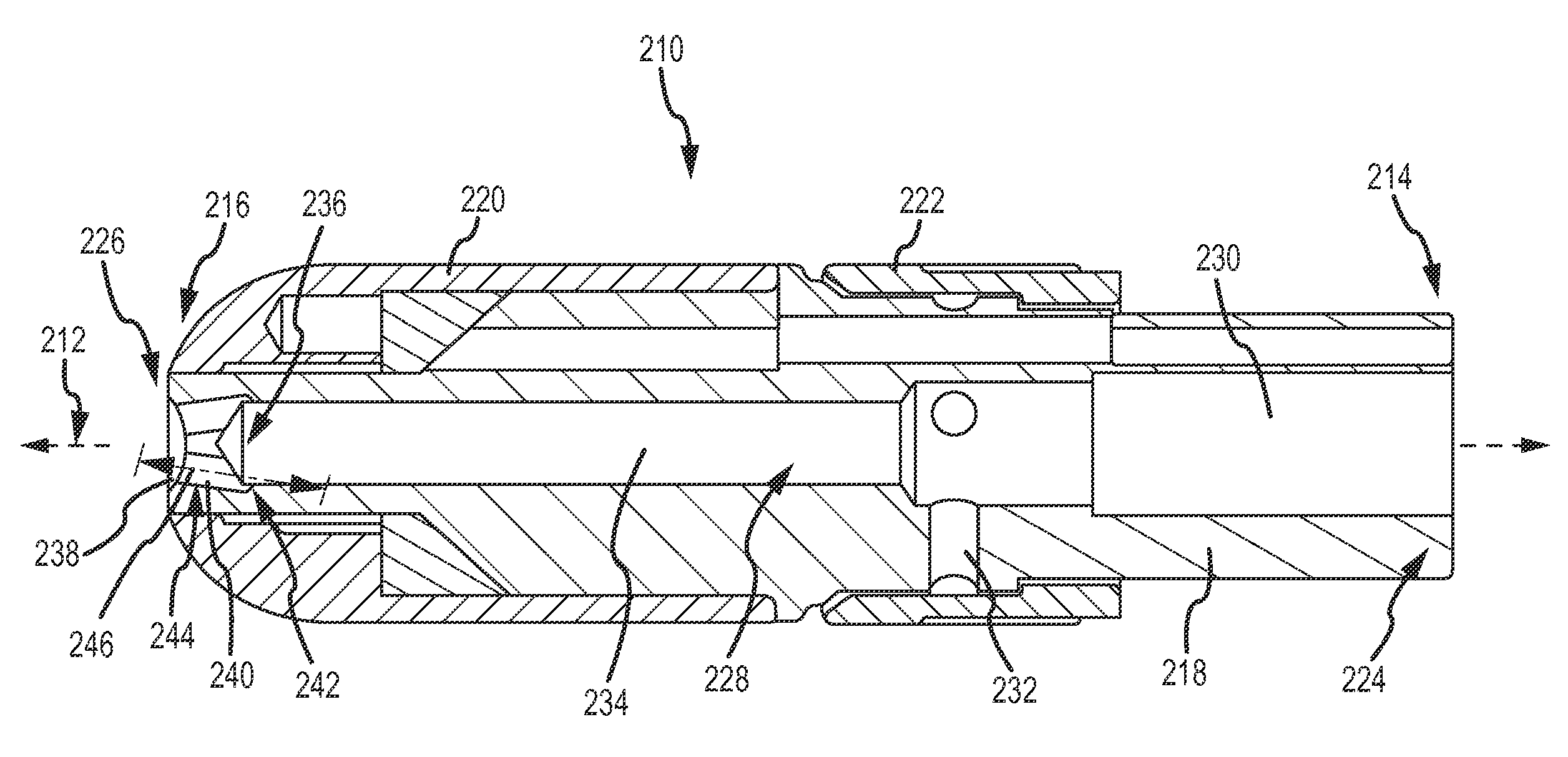
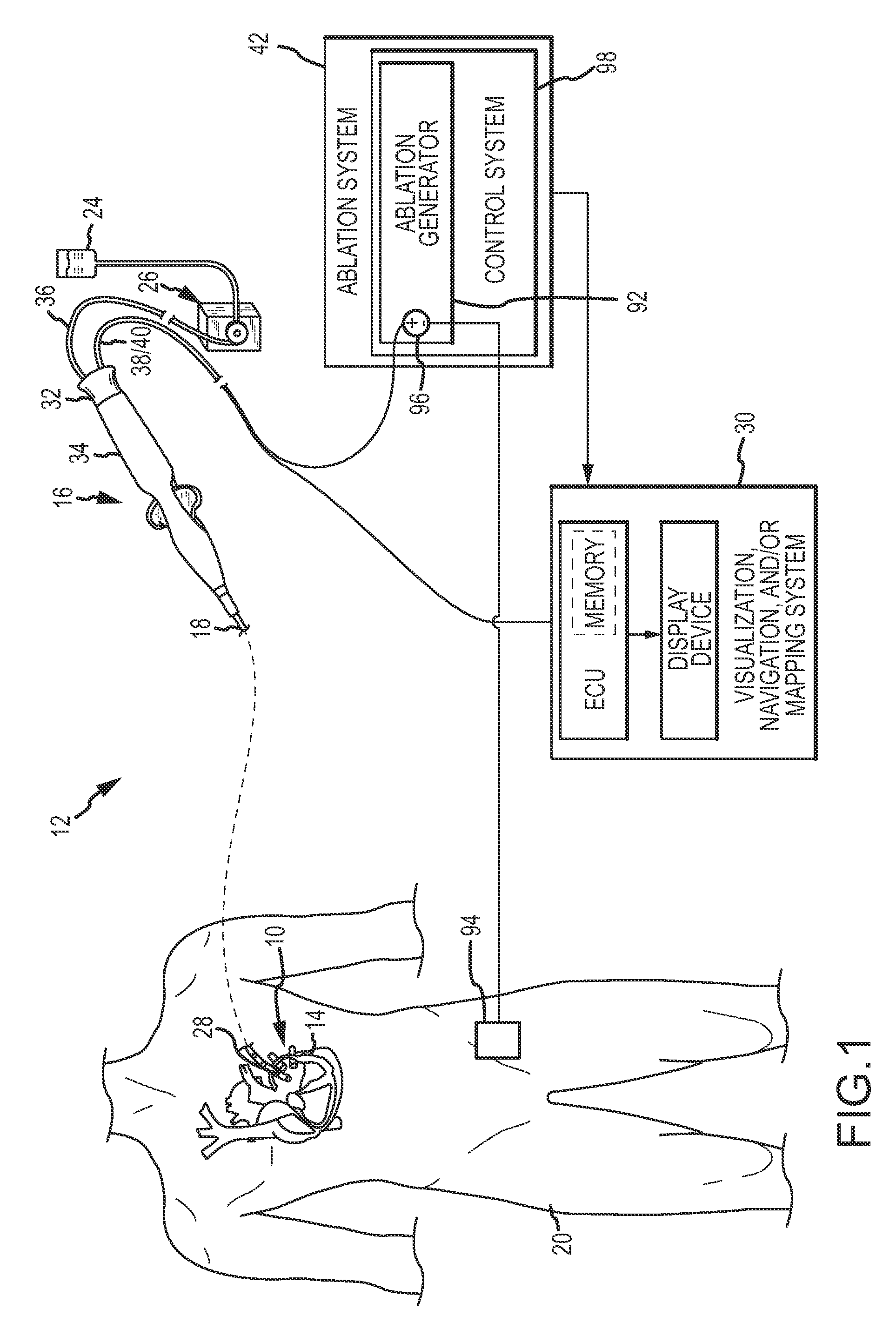
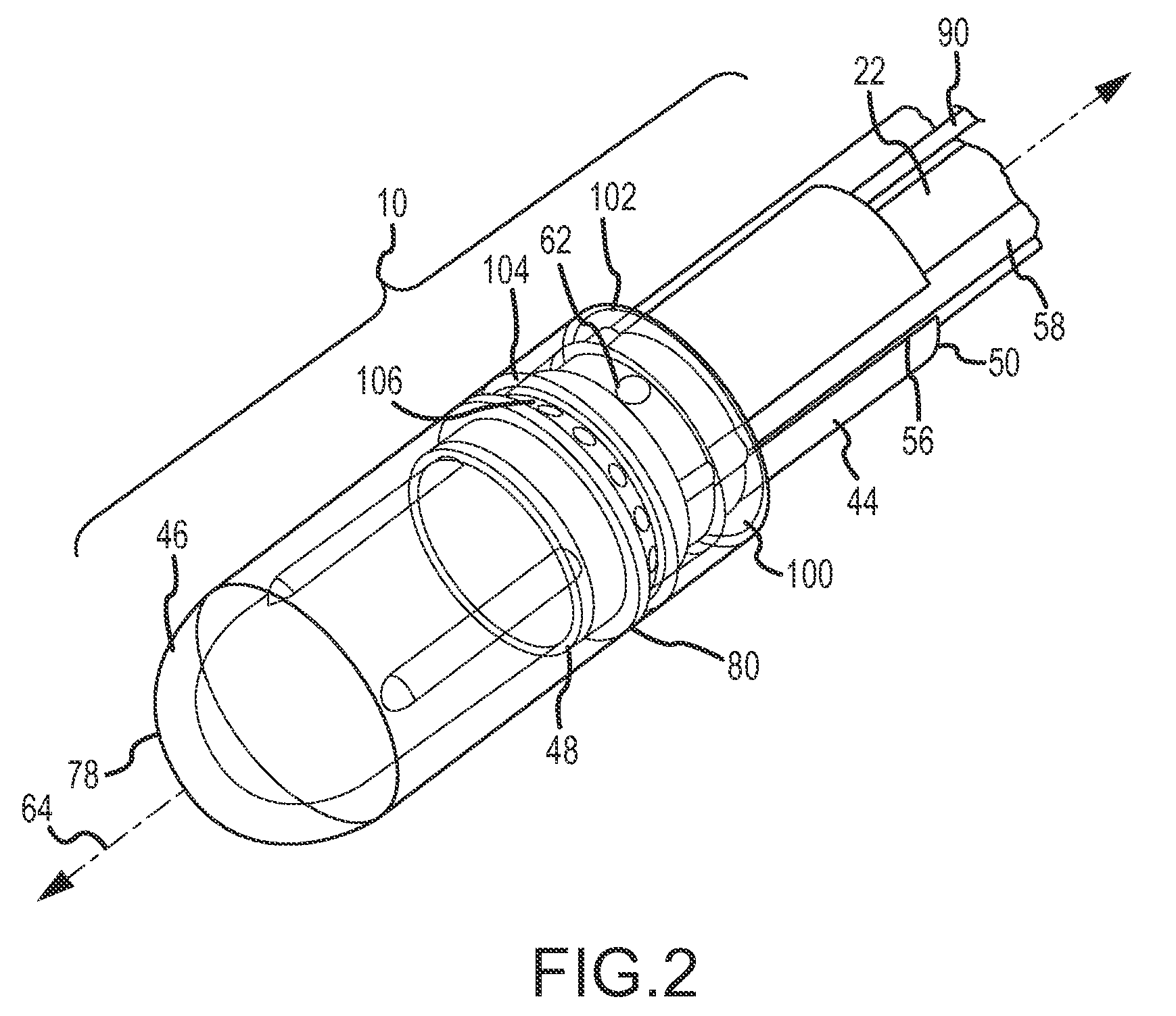
[0029]Various embodiments are directed to apparatuses, systems, and methods for the treatment of tissue. Numerous specific details are set forth to provide a thorough understanding of the overall structure, function, manufacture, and use of the embodiments as described in the specification and illustrated in the accompanying drawings. It will be understood by those skilled in the art, however, that the embodiments may be practiced without such specific details. In other instances, well-known operations, components, and elements have not been described in detail so as not to obscure the embodiments described in the specification. Those of ordinary skill in the art will understand that the embodiments described and illustrated herein are non-limiting examples, and thus it can be appreciated that the specific structural and functional details disclosed herein may be representative and do not necessarily limit the scope of the embodiments, the scope of which is defined solely by the app...


PUM

PropertyMeasurementUnit
lengthaaaaaaaaaa
acute angleaaaaaaaaaa

Abstract

An ablation electrode assembly is provided with improved irrigation cooling of the assembly and ablation site. The assembly includes a proximal end configured to be coupled to a catheter shaft and a distal end configured to deliver ablation energy to tissue. The assembly further includes a fluid manifold extending from the proximal end to the distal end and configured to fluidly communicate with a fluid lumen in the catheter shaft. The fluid manifold defines an axial passageway centered about a longitudinal axis extending in the longitudinal direction of the assembly. The axial passageway has a distal end terminating prior to the distal end of the electrode assembly. The assembly further includes means for creating turbulence in fluid exiting the first axial passageway.

Description

BACKGROUND[0001]a. Field[0002]The instant disclosure relates generally to ablation electrode assemblies and, in particular, to ablation electrode assemblies with improved irrigation of the assembly and ablation site.[0003]b. Background Art[0004]Electrophysiology catheters are used in a variety of diagnostic and / or therapeutic medical procedures to diagnose and / or correct conditions such as atrial arrhythmias, including for example, ectopic atrial tachycardia, atrial fibrillation, and atrial flutter. Arrhythmias can create a variety of conditions including irregular heart rhythms, loss of synchronous atrioventricular contractions and stasis of blood flow in a chamber of a heart which can lead to a variety of symptomatic and asymptomatic ailments and even death.[0005]A medical procedure in which an electrophysiology catheter is used includes a first diagnostic catheter deployed through a patient's vasculature to a patient's heart or a chamber or vein thereof. An electrophysiology cath...

Claims


Application Information

Patent Timeline
Patent Type & Authority Patents(United States)
IPC IPC(8): A61B18/14A61B18/00
CPCA61B18/1492A61B2018/00029A61B2018/00083A61B2018/00107A61B2018/00577A61B2218/002A61B18/12A61B2018/00077A61B2018/00101
Inventor CHRISTIAN, STEVEN C.
Owner ST JUDE MEDICAL ATRIAL FIBRILLATION DIV
Learn More