Abrasive roll assembly

a technology of abrasive roll and roll assembly, which is applied in the direction of grain polishing, cocoa, grain degerming, etc., can solve the problems of time and labor consumption, labor and time consumption, and the overall performance and efficiency of the milling machine, so as to reduce labor, time and cost consumption.

Active Publication Date: 2015-06-30
BUHLER (INDIA) PVT LTD
View PDF6 Cites 0 Cited by
  • Summary
  • Abstract
  • Description
  • Claims
  • Application Information

AI Technical Summary

Benefits of technology

[0008]An object of the present invention is to provide an abrasive roll assembly, which facilitates easy removal and replacing of the worn-out roll assembly without dismantling all components of the milling machine and without altering pulley and axial alignment.
[0009]Another object of the present invention is to provide an abrasive roll assembly, which is simple in construction and facilitates easy maintenance and handling by single untrained person.
[0010]Yet another object of the present invention is to provide a milling machine having an abrasive roll assembly, which minimizes labor, time and cost consumption during maintenance and replacement of worn-out roll assembly.
[0011]According to one aspect, the present invention, which achieves the objectives, relates to an abrasive roll assembly comprising an abrasive roll element configured for milling food grains. An abrasive roll flange is composed of a projecting member formed on its outer periphery, a set of through holes configured for mounting the abrasive roll flange to an adjacent flange by means of fasteners, a set of projecting lugs formed on its upper portion, with guiding and resting portions, a set of projecting pads arranged with threaded holes for mounting the adjacent flange, and a set of guiding members circumferentially spaced apart each other to form a set of openings for entry and exit of the adjacent flange. A supporting plate is placed in opposite to the projecting member of the abrasive roll flange, such that the supporting plate is fastened to the abrasive roll flange using fasteners to secure and hold the abrasive roll element. After inserting the abrasive roll assembly from bottom through openings of the adjacent flange, the abrasive roll assembly is rotated to make the resting portion of each projecting lug of the abrasive roll flange resting on the surface of each guiding member of the adjacent flange, such that each through hole of the abrasive roll flange is aligned with threaded hole in each projecting pad of the adjacent flange for mounting the abrasive roll assembly to the adjacent flange, which ensures centre axial alignment of both the abrasive roll assembly and the adjacent flange with respect to a main shaft of a milling machine. Such arrangement of abrasive roll assembly facilitates easy removal and replacing of the worn-out roll assembly without dismantling all components of the milling machine and without altering pulley and axial alignment.
[0016]The rotary movement of the main shaft is transferred to the conveyor assembly for driving and rotating one or more abrasive roll assemblies attached to it, which evenly distributes rotary motion from top to bottom of the milling machine and ensures co-linearity of axial centre of the conveyor assembly and the one or more abrasive roll assemblies in relation to the main shaft. The arrangement of conveyor assembly and abrasive roll assemblies in this milling machine minimizes labor, time and cost consumption during maintenance and replacement of worn-out roll assembly.

Problems solved by technology

Normally, the last or bottom most abrasive roll assembly can easily and rapidly wears in comparison with other abrasive roll assemblies in the milling machine during use.
The worn-out last abrasive roll assembly affects overall performance and efficiency of the milling machine, and therefore it has to be replaced after the specific time.
Further, the disassembling of milling machine is very time and labor consuming and too tedious, as the construction of rotor main shaft is complicated and the replacement of bottom worn-out abrasive roll requires dismantling of rotor shaft assembly and various other parts of the milling machine, which increases repair and maintenance time and disturbs pulley and axial alignment of the milling machine.
Hence, it increases the difficulty of assembly and disassembly of each component, and also increases installation time and maintenance cost of the milling machine.

Method used


Image

  • Abrasive roll assembly
  • Abrasive roll assembly
  • Abrasive roll assembly

Examples


Embodiment Construction

[0027]The present invention will be described herein below with reference to the accompanying drawings.

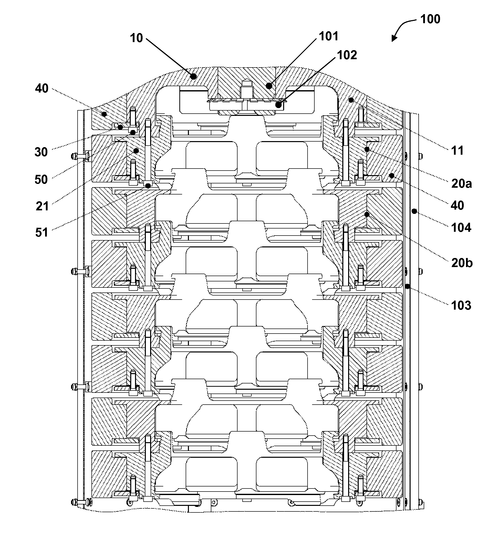
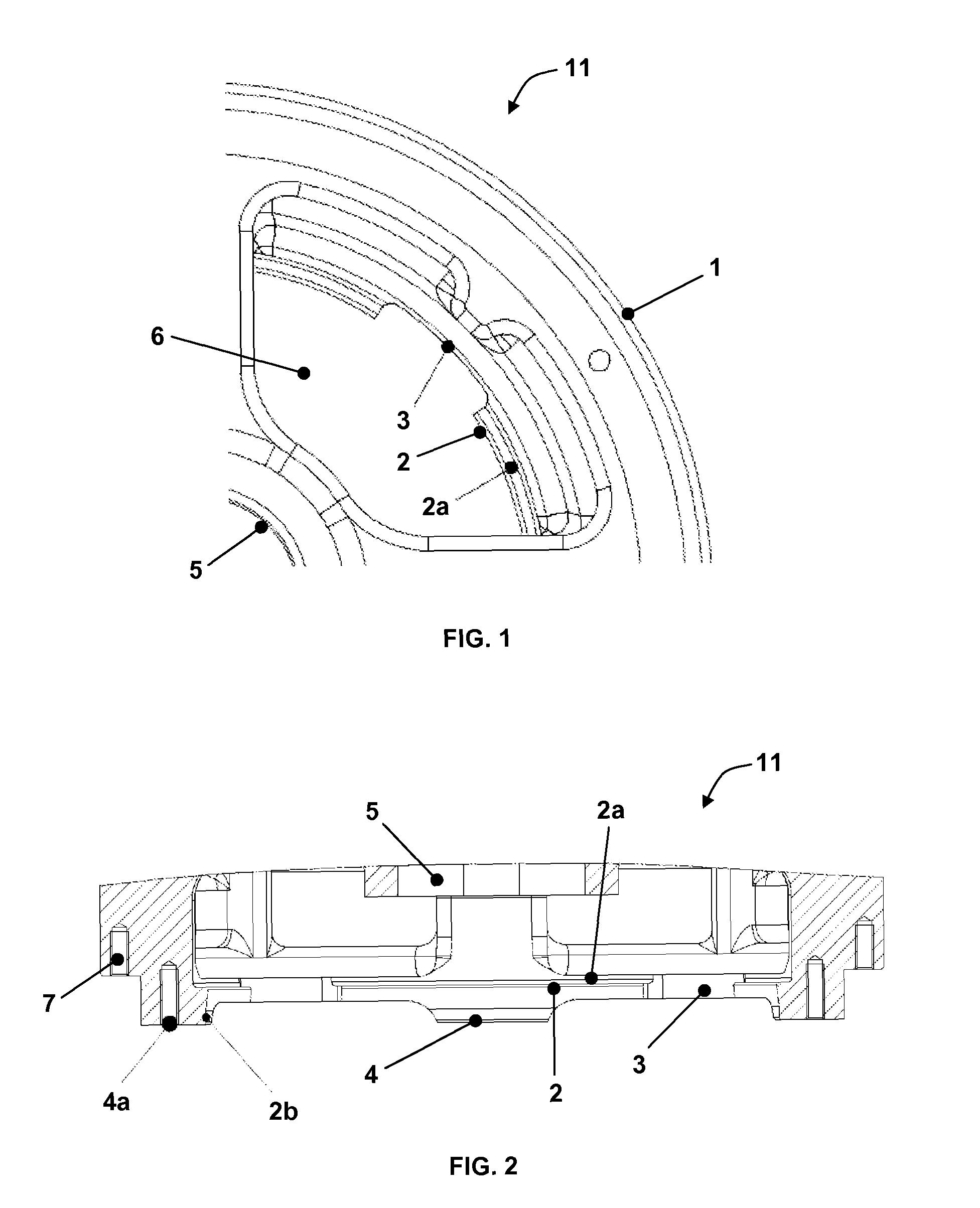
[0028]Referring to FIG. 1, a partial view of a screw conveyor flange 11 is illustrated, in accordance with an exemplary embodiment of the present invention. A conveyor assembly 10 comprises an abrasive roll element 40 configured for milling food grains, a screw conveyor flange 11 and a supporting plate 30. The conveyor flange 11 is assembled with a screw conveyor (not shown) and is coupled to a main shaft 101 of a milling machine 100 by means of locking nut 102. The conveyor flange 11 has a central opening 5 for receiving the main shaft 101 of the milling machine 100, as shown in FIG. 2, which illustrates a sectional front view of the screw conveyor flange 11, in accordance with an exemplary embodiment of the present invention. The screw conveyor flange 11 consists of a projecting member 1, a set of circumferentially spaced projecting pads 4, a set of circumferentially spaced inter...


PUM


Abstract

The present invention relates to an abrasive roll assembly, a conveyor assembly and a milling machine having the same. The abrasive roll assembly comprises an abrasive roll element configured for milling food grains.

Description

CROSS REFERENCE TO RELATED APPLICATIONS[0001]This application claims the benefit under 35 U.S.C. §371 of International Application No. PCT / IN2010 / 000699, filed on Oct. 27, 2010, International Publication No. WO 2012 / 056461 A1, which is incorporated by reference herein.FIELD OF THE INVENTION[0002]The present invention relates to milling machines, specifically vertical abrasive type milling machines for food grains. The present invention particularly relates to an abrasive roll assembly for the vertical abrasive type milling machine.BACKGROUND OF THE INVENTION[0003]Abrasive roll assemblies are commonly used in a milling machine such as vertical abrasive type milling machine, having a milling chamber for polishing or whitening food grains, in particular rice grains. In the vertical abrasive type milling machine, the food grains to be milled are freely supplied from a food grain feeding system to the vicinity of the screw conveyor, through which the food grains are supplied to the milli...

Claims


Application Information

Patent Timeline
Patent Type & Authority Patents(United States)
IPC IPC(8): B02C4/30B02B3/04B02C4/28
CPCB02C4/30B02B3/04B02C4/286
Inventor SUBBANNAVAR, CHAITHANYA B.KUMAR, NAVEEN H. C.
Owner BUHLER (INDIA) PVT LTD
Why Eureka
Try Eureka