Method for diagnosing an engine

a technology for engine operation and engine vaporization, which is applied in the direction of machines/engines, electrical control, lighting and heating apparatus, etc., can solve the problems of engine misfire, more difficult starting and operating the engine, and more difficult engine start-up and operation, so as to increase or decrease the vaporization of fuel within the engine, increase or decrease the effect of fuel vaporization

Inactive Publication Date: 2015-06-30
FORD GLOBAL TECH LLC
View PDF13 Cites 3 Cited by
  • Summary
  • Abstract
  • Description
  • Claims
  • Application Information

AI Technical Summary

Benefits of technology

[0002]Internal combustion engines in vehicles may be subject to a wide range of operating conditions and fuels. The operating conditions may increase or decrease fuel vaporization within the engine, thereby making it more difficult to start and operate the engine. Further, different fuel distributors may supply fuels that have higher or lower volatility than fuels supplied by other fuel distributors. The volatility of the fuel may also make starting the engine more difficult. One consequence of operating the engine over a wide range of conditions with varying fuel types is engine misfire. An air-fuel mixture introduced to the cylinder may not combust or may partially combust as a result of low fuel volatility during colder temperatures. In some engines, injected fuel amount, spark timing, and / or the effective compression ratio may be adjusted to improve the possibility of combusting the air-fuel mixture and reducing misfire. However, it may not be desirable to adjust an amount of fuel supplied to an engine, engine spark timing, or effective compression ratio unless misfire is detected.
[0003]Engine misfire may be detected by monitoring engine speed. If an air-fuel mixture in a cylinder does not combust or partially combusts, engine torque may be reduced. As a result, engine speed may decline for at least a portion of an engine cycle. However, changes in engine speed related to misfire may be less noticeable for engines having a higher number of cylinders. For example, it may be more difficult to detect a misfire of an eight cylinder engine as compared to a four cylinder engine. Additionally, it may be more difficult to detect a misfire at higher engine speeds since engine combustion events are spaced closer together in time.
[0005]Engine misfire may be determined from a position of a turbocharger waste gate and / or an amount of current supplied to a waste gate actuator to control position of the turbocharger waste gate. In particular, pressure from a combusted mixture increases pressure in the exhaust manifold when exhaust is released from a cylinder via opening a cylinder exhaust valve. The increased exhaust manifold pressure can exert force on a turbocharger waste gate causing the position of the waste gate to deflect from a desired position. The deflection of the waste gate may be indicative of a misfire. For example, a cylinder combusting an air-fuel mixture may generate a first pressure in a cylinder when the air-fuel mixture completely combusts. On the other hand, an equivalent air-fuel mixture may generate a second, lower pressure, when the air-fuel mixture is only partially combusted. Thus, the waste gate position may change by a greater amount from a desired position when the air-fuel mixture is completely combusted and released from the cylinder to the exhaust manifold. As such, the waste gate position may be a good indicator of whether or not misfire occurs in an engine cylinder. And, once misfire is detected, cylinder pressure may be increased by adjusting an actuator that reduces the possibility of misfire.
[0006]The present description may provide several advantages. Specifically, the approach may provide a reliable way to determine engine misfire in turbocharged engines. Additionally, the approach may provide a cross-check to other misfire detection methods such as misfire detection using engine speed. Further, the approach may be more reliable than other engine misfire detection schemes during particular engine operating conditions, such as during engine starting.

Problems solved by technology

The operating conditions may increase or decrease fuel vaporization within the engine, thereby making it more difficult to start and operate the engine.
The volatility of the fuel may also make starting the engine more difficult.
One consequence of operating the engine over a wide range of conditions with varying fuel types is engine misfire.
However, it may not be desirable to adjust an amount of fuel supplied to an engine, engine spark timing, or effective compression ratio unless misfire is detected.
As a result, engine speed may decline for at least a portion of an engine cycle.
For example, it may be more difficult to detect a misfire of an eight cylinder engine as compared to a four cylinder engine.
Additionally, it may be more difficult to detect a misfire at higher engine speeds since engine combustion events are spaced closer together in time.

Method used


Image

  • Method for diagnosing an engine
  • Method for diagnosing an engine
  • Method for diagnosing an engine

Examples


Embodiment Construction

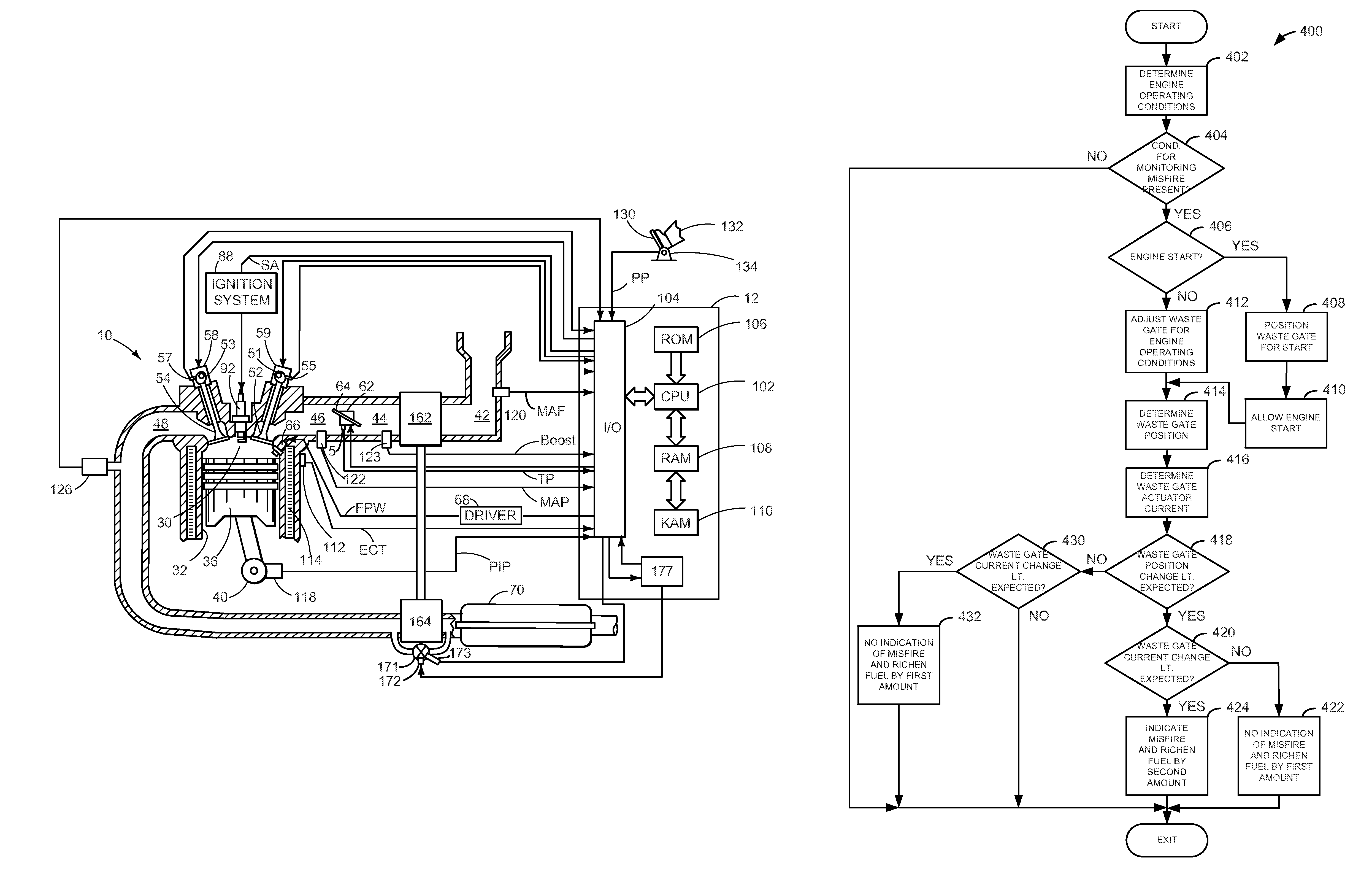
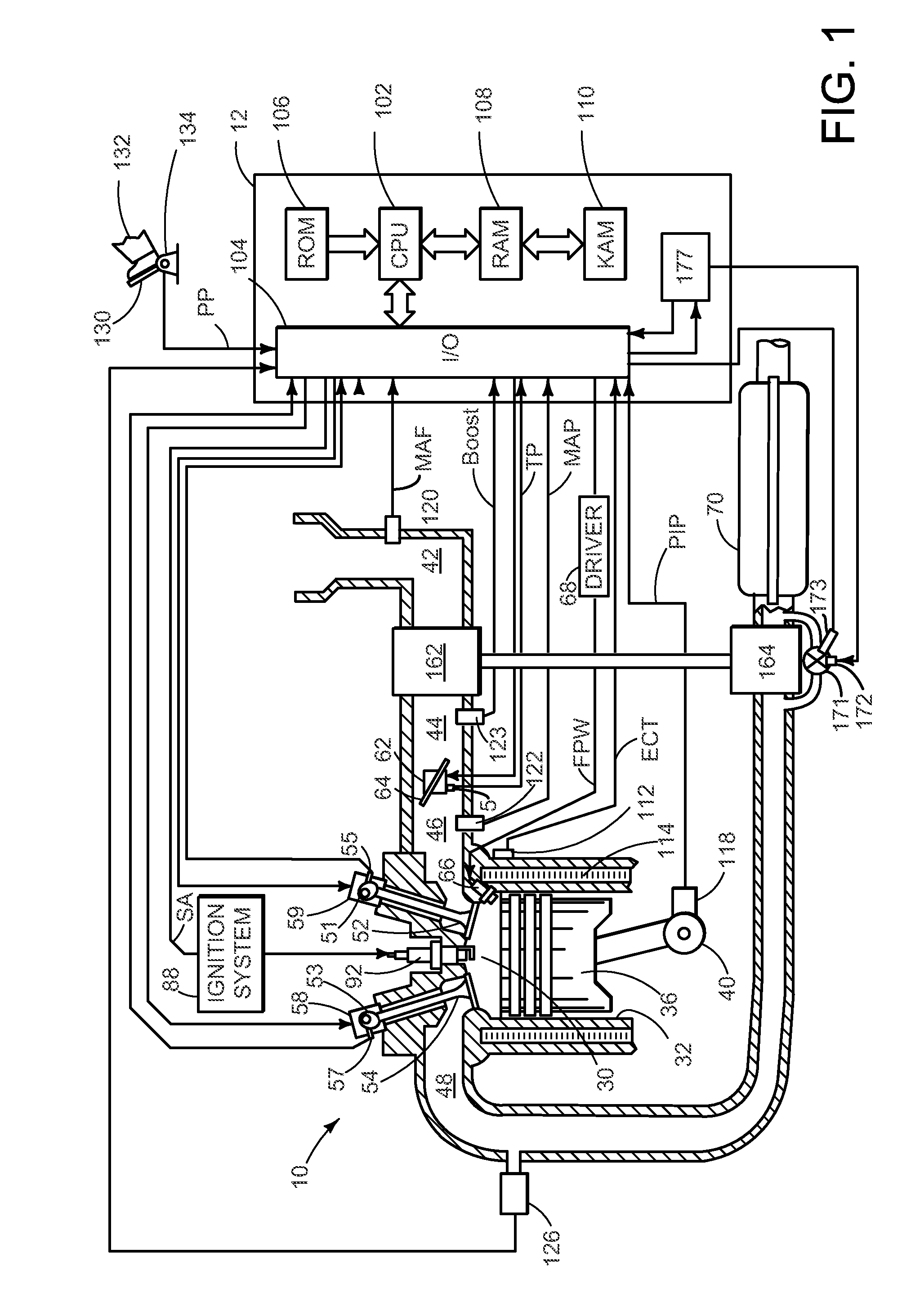
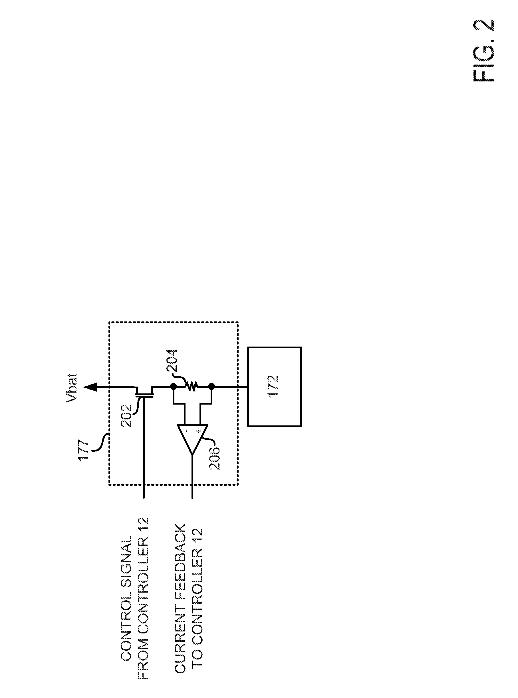
[0014]The present description is related to detecting and compensating for engine misfire. In one non-limiting example, the engine may be configured as illustrated in FIG. 1. The engine includes a turbocharger with a waste gate, and the waste gate includes a position sensor to determine a position of the waste gate. FIG. 2 shows an example circuit for determining an amount of current supplied to the waste gate when the waste gate is an electrically actuated waste gate. FIG. 3 shows an example sequence where waste gate position and / or current are a basis for determining engine misfire. Finally, FIG. 4 shows an example method for detecting and compensating engine misfire.

[0015]Referring to FIG. 1, internal combustion engine 10, comprising a plurality of cylinders, one cylinder of which is shown in FIG. 1, is controlled by electronic engine controller 12. Engine 10 includes combustion chamber 30 and cylinder walls 32 with piston 36 positioned therein and connected to crankshaft 40. Com...


PUM


Abstract

A method for operating an engine in response to a waste gate position is presented. In one example, the method adjusts an actuator to reduce the possibility of misfire in an engine cylinder in response to waste gate position. In this way, it may be possible to adjust engine operation for varying engine operating conditions.

Description

FIELD[0001]The present description relates to a method for diagnosing operation of an engine. The method may be particularly useful for engines that include a turbocharger.BACKGROUND AND SUMMARY[0002]Internal combustion engines in vehicles may be subject to a wide range of operating conditions and fuels. The operating conditions may increase or decrease fuel vaporization within the engine, thereby making it more difficult to start and operate the engine. Further, different fuel distributors may supply fuels that have higher or lower volatility than fuels supplied by other fuel distributors. The volatility of the fuel may also make starting the engine more difficult. One consequence of operating the engine over a wide range of conditions with varying fuel types is engine misfire. An air-fuel mixture introduced to the cylinder may not combust or may partially combust as a result of low fuel volatility during colder temperatures. In some engines, injected fuel amount, spark timing, and...

Claims


Application Information

Patent Timeline
Patent Type & Authority Patents(United States)
IPC IPC(8): F02D23/00F02D41/22F02B5/00F02B3/00F02D41/14F02P5/00F02M51/00F23N5/00F02D41/00F02B37/18
CPCF02D41/0007F02D41/1454F02D41/221F02D2200/0404F02D2200/0406F02D2200/1015Y02T10/40Y02T10/144F02B37/18Y02T10/12
Inventor MCCONVILLE, GREGORY PATRICKGALE, ALLAN ROY
Owner FORD GLOBAL TECH LLC
Why Eureka
Try Eureka