Internal combustion engine

a technology of internal combustion engine and lubricating oil, which is applied in the direction of auxillary lubrication, non-mechanical valves, valve drives, etc., can solve the problems of affecting the performance of the engine, affecting the efficiency of the engine, and bringing one of the components into the inappropriate state, etc., and achieves the effect of efficient lubrication of the respective elements

Inactive Publication Date: 2006-08-22
TOYOTA JIDOSHA KK
View PDF18 Cites 0 Cited by
  • Summary
  • Abstract
  • Description
  • Claims
  • Application Information

AI Technical Summary

Benefits of technology

[0017]In the embodiment of the invention, the properties of the lubricating oil supplied through the lubricating oil passage for the electromagnetically driven valve are different from the lubricating oil supplied through the other lubricating oil passage for efficiently lubricating the respective element...

Problems solved by technology

If the electromagnetically driven valve is employed in the above-structured internal combustion engine, the drawback may occur as described below.
Accordingly, the common use of the lubricating oil both for the electromagnetically driven valve and the engine body may cause any one of them to be brought into the inappropriate state with respect to its performance.
It is, therefore, not appropriate to us...

Method used


Image

  • Internal combustion engine
  • Internal combustion engine
  • Internal combustion engine

Examples


first embodiment

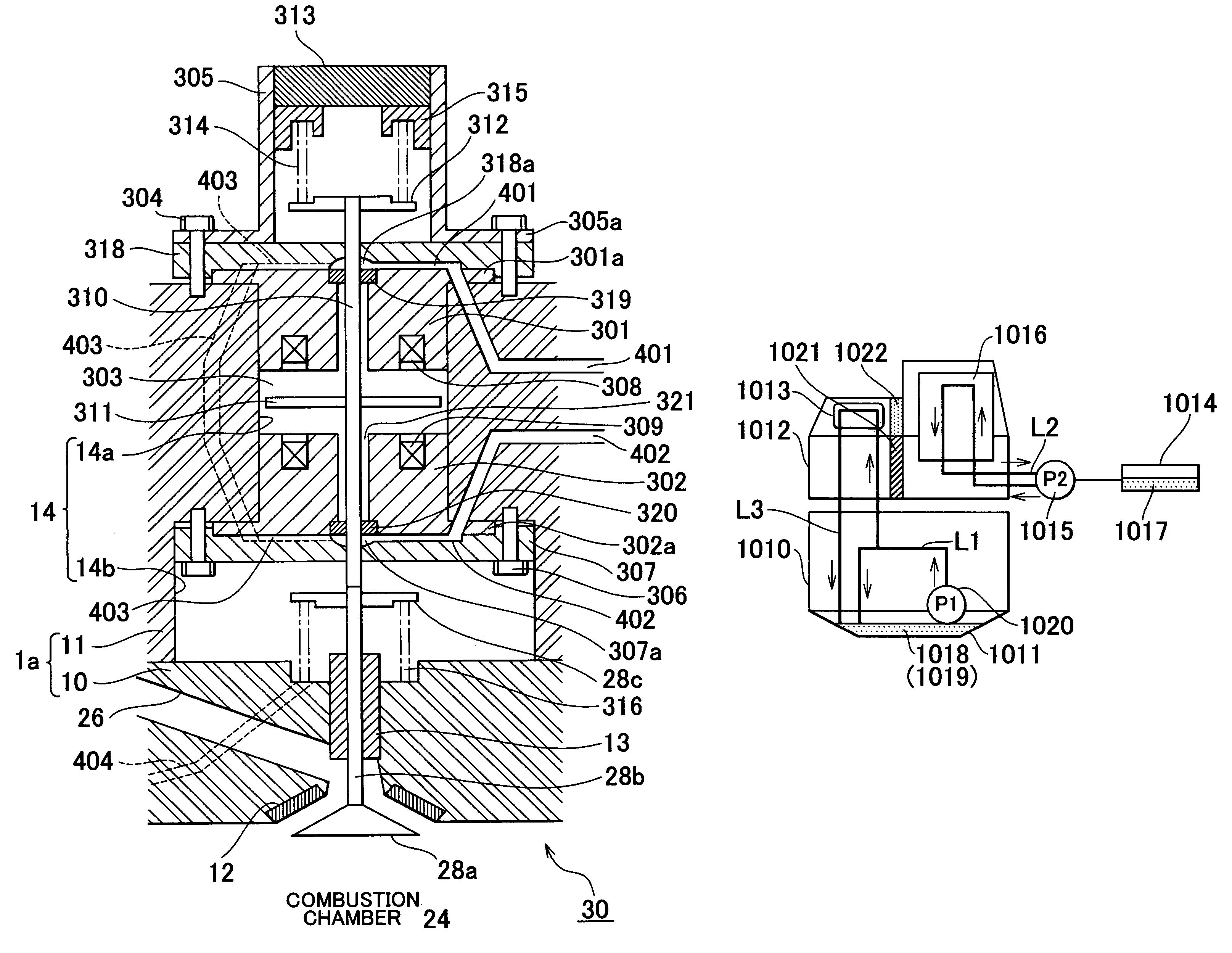
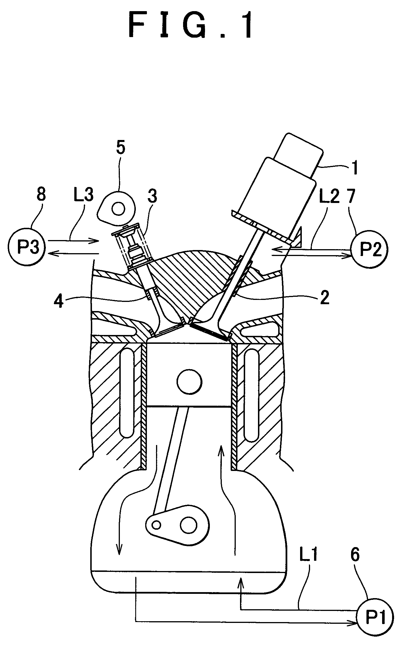
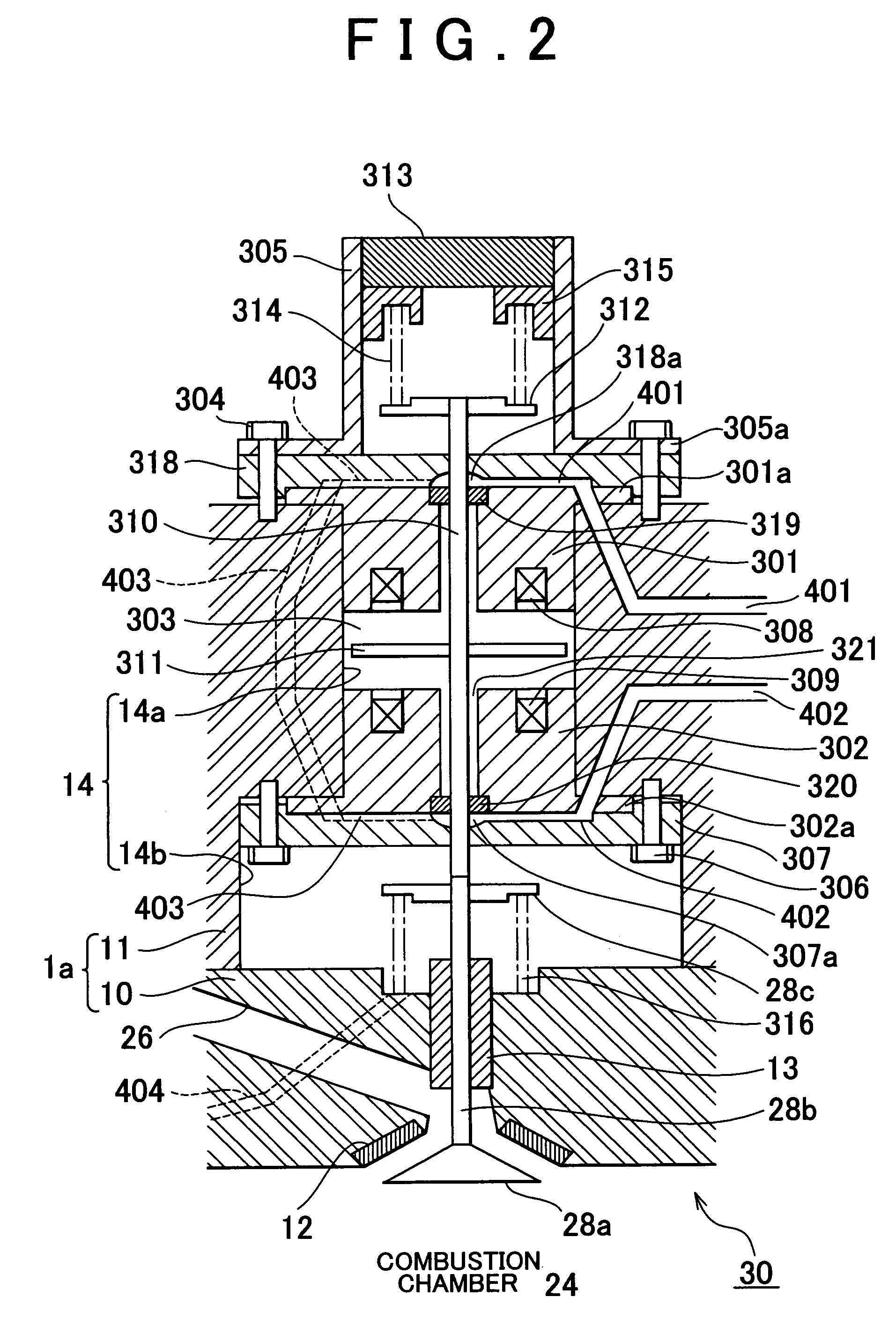
[0049]FIG. 4 is a view showing a first embodiment corresponding to (A) having the lubricating oil passage L1 for the cylinder block and the lubricating oil passage L2 for the electromagnetically driven valve in the cylinder head are structured to function independently. The lubricating oil passage L1 supplies the lubricating oil to the lubricating oil passage L3 for the cam driven valve.

[0050]The lubricating oil supply path will be described referring to FIG. 5. The lubricating oil pumped by the oil pump P1 from the oil pan 1011 is filtrated through an oil filter, and then supplied from a main oil hole to the cylinder head. The lubricating oil flows through an exhaust cam journal (including the camshaft 1013) for the valve for driving the exhaust valve from the cylinder head for direct lubrication, and returns to the oil pan 1011. A part of the lubricating oil flows through a scissors gear after flowing through the exhaust cam journal, and the returns to the oil pan 1011. The lubric...

second embodiment

[0055]As shown in FIG. 6, a second embodiment has a structure corresponding to (B) where the lubricating oil passage L1 for the crank shaft of the cylinder block, and the lubricating oil passage L2 for the electromagnetically driven valve and the cam driven valve in the cylinder head are separately provided. The lubricating oil passage L2 is structured to supply the lubricating oil both to the actuator for the electromagnetically driven valve 101 in the cylinder head and the cam shaft for the cam driven valve 1013.

[0056]The lubricating oil for the engine as shown in FIG. 3 is supplied through the lubricating oil passage L1, and the lubricating oil for the electromagnetically driven valve or the cam driven valve is supplied through the lubricating oil passage L2. Each viscosity of the respective types of the lubricating oil is different as shown in FIG. 3, that is, the viscosity of the lubricating oil in the lubricating oil passage L1 is relatively higher than that of the lubricating...

third embodiment

[0057]As shown in FIG. 7, a third embodiment has a structure corresponding to (B) where the lubricating oil passages L1 and L2 are independently provided like the second embodiment. The lubricating oil passage L2 extends to the actuator for the electromagnetically driven valve in the cylinder head and further to the camshaft for the cam driven valve so as to lubricate both valves with the same type of the lubricating oil.

[0058]Supposing that elements in the cylinder block can be lubricated with the lubricating oil at relatively lower viscosity, the lubricating oil 1017 for the electromagnetically driven valve or the lubricating oil 1019 for the cam driven valve may be used as the lubricating oil supplied through the lubricating oil passages L1 and L2. In this embodiment, the lubricating oil passage L1 is separately provided from the lubricating oil passage L2. This makes it possible to prevent the use of the lubricating oil that has been degraded by lubricating the elements in the c...


PUM


Abstract

In an internal combustion engine having an electromagnetically driven valve for driving one of an intake valve and an exhasut valve, at least a lubricating oil passage to a head section including a lubricating oil passage to the electromagnetically driven valve is provided independently from other lubricating oil passage such that the lubricating oil for the electromagnetically driven valve is not mixed with the other lubricating oil. A lubricating device is allowed to have a portion where the lubricating oil is commonly used so long as the lubricating oil for the electromagnetically driven valve and the lubricating oil for the other elements are not mixed.

Description

[0001]The disclosure of Japanese Patent Application No.2002-247590 filed on Aug. 27, 2002, including the specification, drawings and abstract are incorporated herein by reference in its entirety.BACKGROUND OF THE INVENTION[0002]1. Field of Invention[0003]The invention relates to an internal combustion engine and more particularly, to a lubricating oil passage in the internal combustion engine.[0004]2. Description of Related Art[0005]In an internal combustion engine, a cam driven valve has been generally employed for an intake valve and an exhaust valve. Recently, an electromagnetically driven valve has been employed as the intake valve or the exhaust valve in place of the cam driven valve. For example, JP-A-11-36829 discloses a full cam-less structure in which the electromagnetically driven valve is employed as both the intake and the exhaust valves, and lubricating oil is supplied to a portion that slides along with the opening / closing operation of the valve body. JP-A-2001-355417 ...

Claims


Application Information

Patent Timeline
IPC IPC(8): F01L9/04F01M1/06F01L9/20F01M9/10F01M11/02F02D13/02
CPCF01L9/04F01M9/10F01L1/143F01L2009/0436F01L2009/048F01L2001/0535F01L2009/408F01L2009/2136F01L9/20
Inventor KATSUMATA, SHOUJI
Owner TOYOTA JIDOSHA KK
Why Eureka
Try Eureka