Desmodronic shaft and yoke assembly for translating linear to rotary motion

a technology of linear movement and assembly, which is applied in the direction of positive displacement engines, piston engines, engine components, etc., can solve the problems of significant disadvantages and limitations of internal combustion engines, and the inability to use convention scotch yokes, so as to improve combustion efficiency and improve combustion efficiency

Inactive Publication Date: 2015-06-30
EXODUS R&D INT PTE
View PDF6 Cites 0 Cited by
  • Summary
  • Abstract
  • Description
  • Claims
  • Application Information

AI Technical Summary

Benefits of technology

[0023]It should become apparent from a reading of this specification that the assembly provides for greater leverage than either scotch yoke or con-rod engine types in that the interaction between crank and piston is, in part, cam-related. The present invention provides a linear movement mechanism that is rigid, meaning the piston movement is linear and integral with the movement of the yoke structure, and which is able to transform energy to a greater leverage point than conventional engines at the same stroke length. As a result, a leverage effect is established and pressure transferred to the crank is maximised.
[0026]It is the rocking motion or “cam effect” which takes place between 90 and 180 degree shaft rotation, as opposed to sliding or rolling, between the two components through a particular range of angles which distinguishes the assembly from conventional scotch yoke type assemblies and which results in an improved interaction between these components and a much greater torque range.
[0027]Thus, the assembly of the invention incorporates a rotatable shaft that is engageable with an inner surface of a yoke structure, the shaft including what is referred to herein as a leverage means including an outer peripheral edge adapted to contact the inner surface of a yoke structure along an arced surfaces associated with the leverage means at any one time throughout the rotation of the shaft. The components are dimensioned such that during at least a range of angles, there is a “rocking motion” interaction between an arced surface of the leverage means and the inner surface of the yoke (analogous to the motion of a rocking horse rocking with the floor) which importantly causes a constant contact force to be transferred from the yoke structure to the shaft. This effect is referred to herein as a “cam effect”.
[0031]In preference the cam follower member and yoke structure inner surface are dimensioned such that the shaft rotates between 0 and 90 degrees without any such rotary movement being translated on rectilinear motion of the yoke structure. Thus, when applied to a combustion engine, the present invention improves combustion efficiency by also introducing a dwell time at top dead centre.
[0032]In preference the cam follower member and yoke structure inner surface are dimensioned such that the shaft rotates between 180 and 270 degrees without any such rotary movement being translated on rectilinear motion of the yoke structure. Thus, when applied to a combustion engine, the present invention improves combustion efficiency by also introducing a dwell time at bottom dead centre.
[0035]In a still further preferred form of the invention, the shaft is a desmodronic shaft and each of said first and second quarter circle edges are adjacent and flush with said semi-circular edge, wherein at least a portion of the second quarter circle edge, the semi-circular edge at a portion adjacent the second quarter circle edge, or both, is sawn off to expose a rolling element housed substantially inside the cam follower member such that only a partial circumference of the rolling element extends out from the cam follower member footprint, a central axis of the rolling element being disposed along a base centre line of said semicircular edge. The rolling element contacts said yoke structure inner surface during said “cam effect”, the rolling element being of equal radius to said arced surface, said arced surface including a sawn off tip to allow for said rolling element to contact said yoke structure when said tip would otherwise have made contact with said inner surface. The use of an anti-friction or rolling element is particularly important between 90 and 180 degree rotation of the shaft to reduce chatter that would otherwise occur between the contacting surfaces.

Problems solved by technology

Nonetheless, time has proven that these types of internal combustion engines do have significant disadvantages and limitations.
The use of convention scotch yokes is not always possible for the most part as the piston stroke is short and the time available for drawing air into the combustion chamber is very short.
This causes combustion at less than the ideal 15 to 1 air / fuel ratio for the fuel which in turn, leaves unburnt fuel to be exhausted as pollutants into the atmosphere.
With the exhausted unburnt fuel goes wasted energy which should have been converted to power to drive the piston.
What effectively is happening in both currently available slider crank engines as well as Scotch yoke based designs is that there is inefficient coupling between the piston rod and the crank shaft.
This however is not practical in many applications and there are various associated disadvantages.
Scotch yokes therefore have very limited application.

Method used


Image

  • Desmodronic shaft and yoke assembly for translating linear to rotary motion
  • Desmodronic shaft and yoke assembly for translating linear to rotary motion
  • Desmodronic shaft and yoke assembly for translating linear to rotary motion

Examples


first embodiment

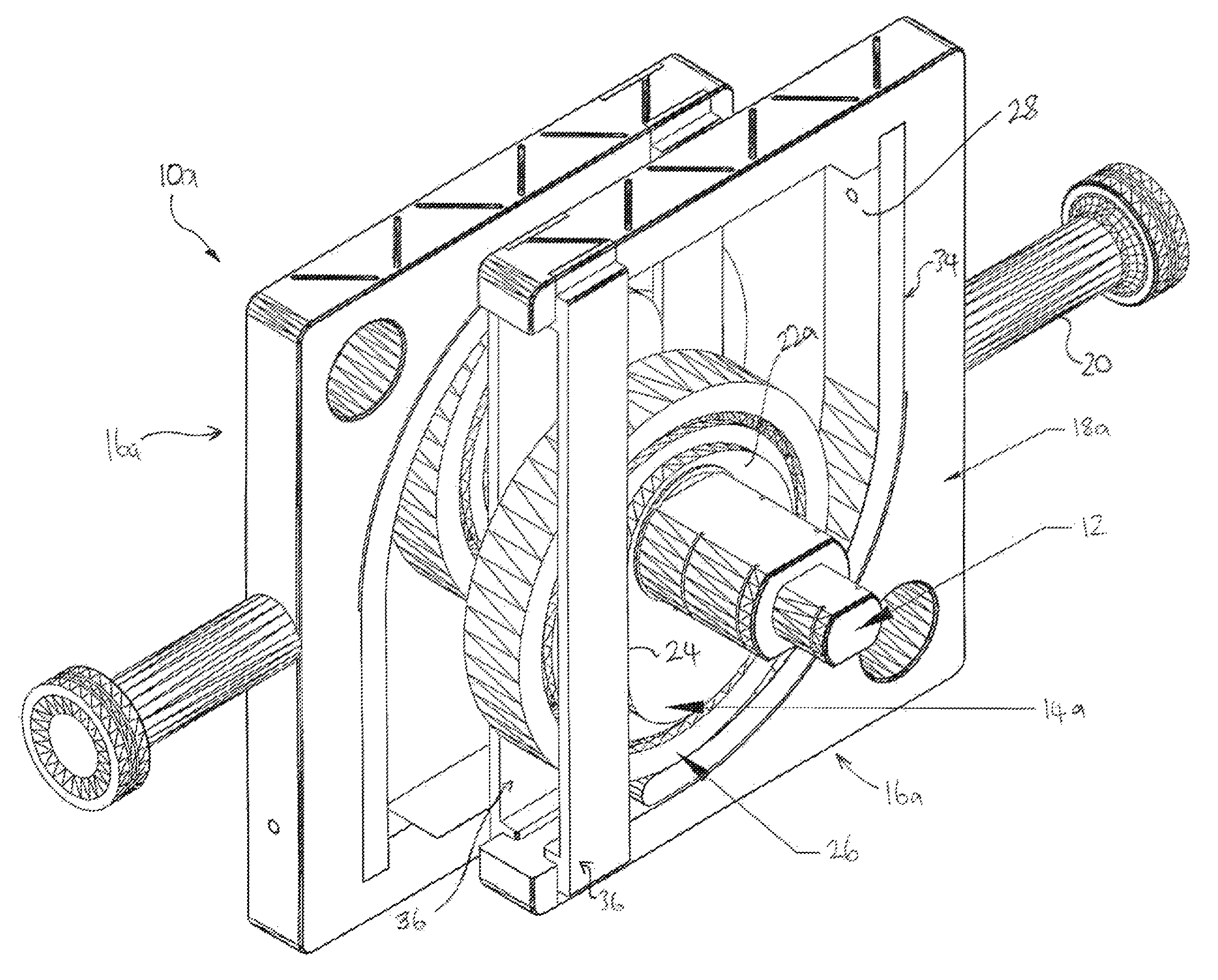
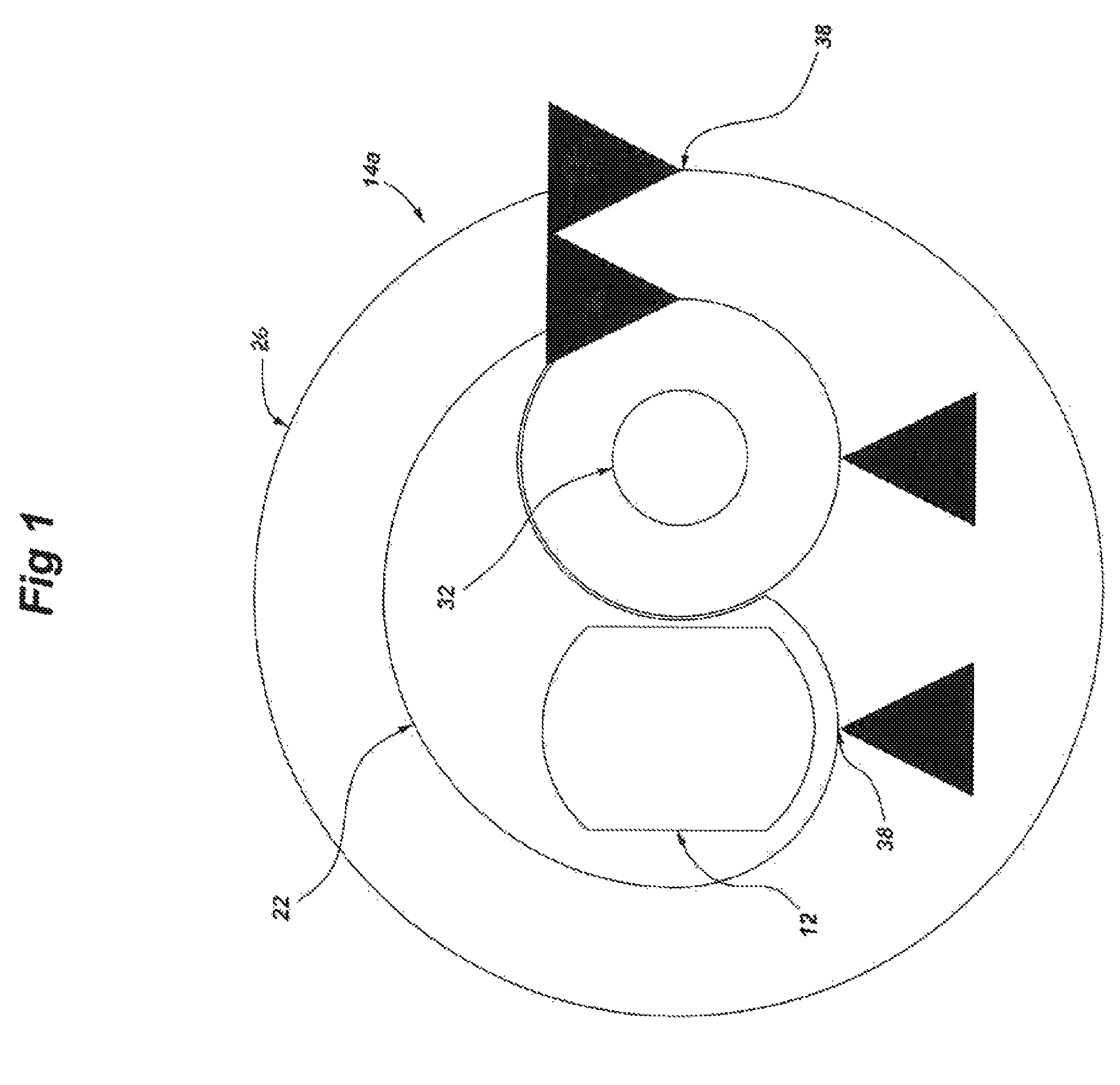
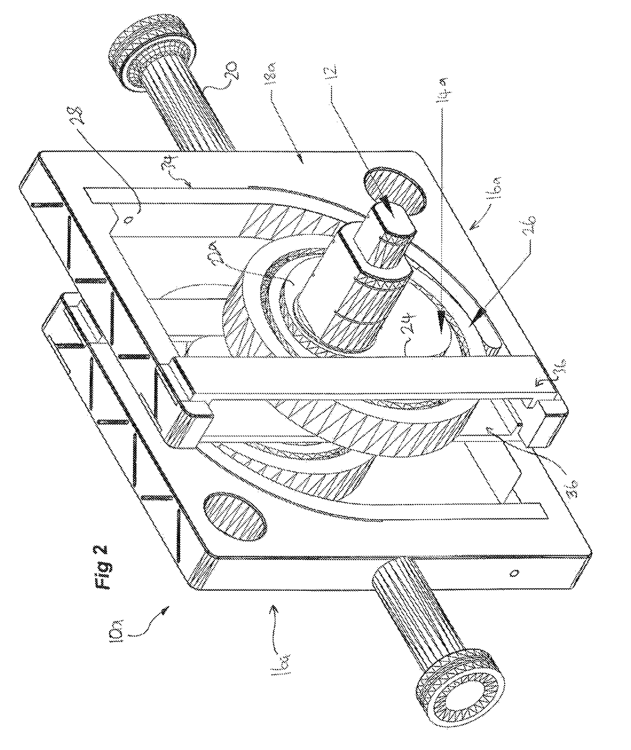
[0057]FIGS. 1-4 illustrate the present invention being an assembly 10a configured for single dwell from 0 through 90 degree rotation of the crank shaft 12, the assembly including a leverage means 14a having two cam follower members 22 built onto the crank shaft 12 and interacting with the yoke structure 18a such that force is carried from the yoke to rotate the crank.

[0058]In particular, the leverage means 14a includes two parallel and laterally spaced cam follower members 22 including arced surfaces adapted to contact respective inner surfaces 24 of the yoke structure 18a, the surfaces 24 being inner surfaces of the yoke structure located at the “base” of the yoke assembly 16a, that is, on the opposite end of the piston 20. The leverage means 14a further includes a large diameter rolling element or bearing 26 extending between the two cam follower members and adapted to contact an arced inner surface 28 of the yoke structure. Disposed inside the larger diameter rolling element 26 i...

second embodiment

[0074]Turning now to FIG. 8 and a preferred form of the invention, there is shown a leverage means 14c forming part of the assembly 10c shown in FIG. 9, the leverage means 14c including a similar cam follower member and yoke structure profile as depicted in the second embodiment but including a hollowed out channel 70 between which is rotatably mounted an internal roller 72. The roller is rotatable about a pin 73. A shaft including a cam follower configured like so and including an internal roller 72 is herein referred to as a desmodronic crank shaft.

[0075]FIGS. 9-10 illustrate the leverage means 14c in use with a linear yoke assembly 16c and it should be appreciated that the yoke structure is essentially the same as that discussed with respect to the second embodiment but having an inner surface configured slightly differently. It is to be understood that the inner surface still includes the main rounded edges of the second embodiment 60 and 62, as well as parallel surfaces 56 and ...


PUM


Abstract

The present invention relates to an assembly for translating linear movement to rotary motion, and in particular to an improved relationship between a linearly reciprocal member such as a yoke structure and associated piston, and a rotatable shaft such as a crank shaft. The invention could be used in any application where motion is to be translated from rotary to linear or vice versa, such as in compressors for example.

Description

CROSS-REFERENCE TO RELATED APPLICATIONS[0001]This application claims the benefit of an Australian provisional application number 2011902573, filed Jun. 30, 2011. The entire disclosure of the prior application is hereby incorporated by reference.FIELD OF THE INVENTION[0002]The present invention relates to an assembly for translating linear movement to rotary motion, and in particular to an improved relationship between a linearly reciprocal member such as a yoke structure and associated piston, and a rotatable shaft such as a crank shaft. The invention could be used in any application where motion is to be translated from rotary to linear or vice versa, such as in compressors for example.BACKGROUND OF THE INVENTION[0003]The internal combustion engine has now been with us for many decades and has become a most familiar design wherein the reciprocating piston uses connecting rods to connect the piston to the crank pins of the crank shaft to translate linear reciprocating motion of the ...

Claims


Application Information

Patent Timeline
Patent Type & Authority Patents(United States)
IPC IPC(8): F01B9/00F01B9/06F16H21/30F01B9/02F02B75/32
CPCF16H21/30F01B9/06F01B9/023F01B9/00F02B75/32Y10T74/1828F01B9/02F02B75/12F02B2275/36F16H21/36
Inventor FLENCHE, GEORGE
Owner EXODUS R&D INT PTE
Why Eureka
Try Eureka