Check patentability & draft patents in minutes with Patsnap Eureka AI!

Proximity mask for ion implantation with improved resistance to thermal deformation

a technology of ion implantation and proximity mask, which is applied in the direction of photomechanical treatment originals, instruments, nuclear engineering, etc., can solve the problems of mask deformation, ineffective or inoperable implanted substrates for the intended purpose,

Active Publication Date: 2015-06-30
VARIAN SEMICON EQUIP ASSOC INC
View PDF7 Cites 1 Cited by
  • Summary
  • Abstract
  • Description
  • Claims
  • Application Information

AI Technical Summary

Benefits of technology

The mask effectively maintains the ion beam pattern by accommodating thermal expansion in a direction parallel to the beam, preventing distortion and ensuring the implanted substrate's integrity.

Problems solved by technology

A problem commonly associated with such masks it that, when exposed to an ion beam projected thereon and therethrough, portions of the mask may heat up and expand, causing the mask to deform.
Such deformation can result in the distortion of a desired implantation pattern, which may render an implanted substrate ineffective or inoperable for its intended purpose.

Method used


Image

  • Proximity mask for ion implantation with improved resistance to thermal deformation
  • Proximity mask for ion implantation with improved resistance to thermal deformation
  • Proximity mask for ion implantation with improved resistance to thermal deformation

Examples


Embodiment Construction

[0017]A device in accordance with the present disclosure will now be described more fully hereinafter with reference to the accompanying drawings, in which preferred embodiments of the device are shown. This device, however, may be embodied in many different forms and should not be construed as being limited to the embodiments set forth herein. Rather, these embodiments are provided so that this disclosure will be thorough and complete, and will fully convey the scope of the device to those skilled in the art. In the drawings, like numbers refer to like elements throughout.

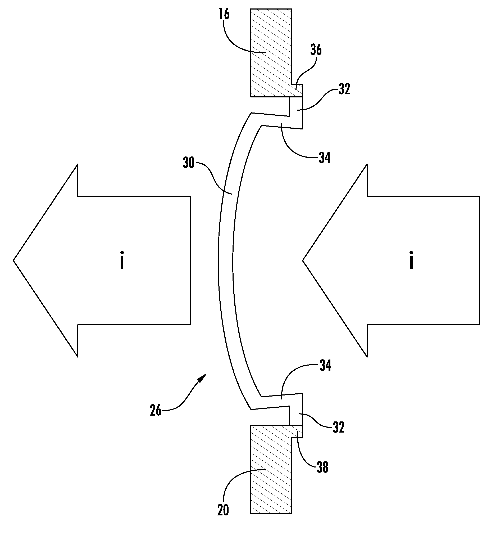
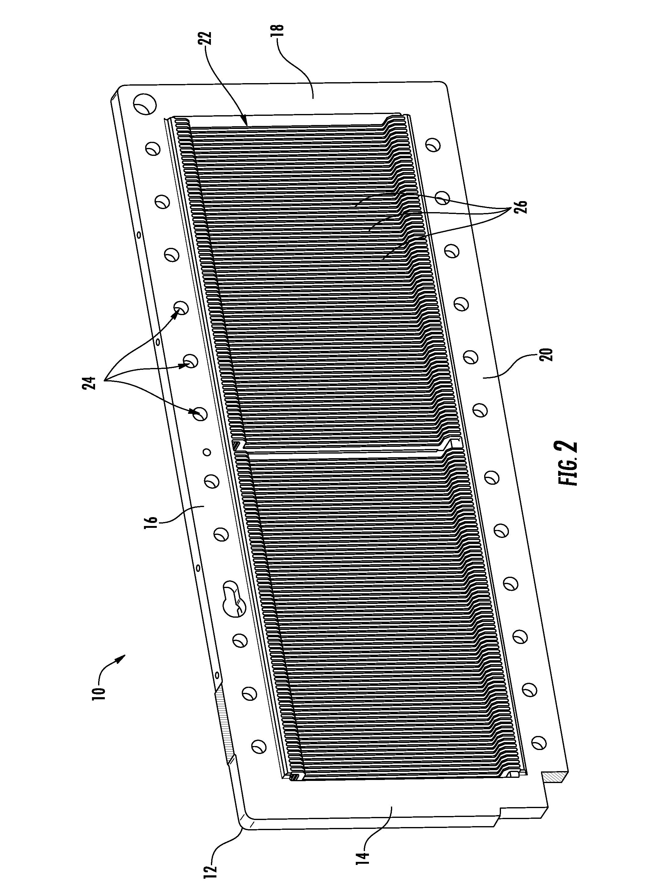
[0018]Referring to FIGS. 1-3, an exemplary ion implanter proximity mask 10 (hereinafter referred to as “the mask 10”) in accordance with the present disclosure is shown. For the sake of convenience and clarity, terms such as “front,”“rear,”“top,”“bottom,”“inwardly,”“outwardly,”“lateral,”“longitudinal,” and “vertical” will be used herein to describe the relative placement and orientation of components of the mask 1...


PUM

PropertyMeasurementUnit
acceptance angleaaaaaaaaaa
thicknessaaaaaaaaaa

Abstract

A proximity mask for ion implantation that is configured to resist thermal deformation in a direction normal to an ion beam projected on and through the mask. The mask may include a frame defining a central aperture and a plurality of ribs disposed within the aperture. The ribs may define a doping pattern and may be configured to deform in a direction normal to an ion beam projected thereon and to resist deformation in a direction orthogonal to an ion beam projected thereon upon being heated. Particularly, at least one of the ribs may include a bridge member, first and second perpendicular support legs extending perpendicularly from the bridge member, and first and second parallel support legs that extend perpendicularly from the first and second perpendicular support legs, respectively. The first and second parallel support legs may be attached to the frame.

Description

FIELD OF THE DISCLOSURE[0001]The disclosure relates generally to the field of semiconductor device fabrication, and more particularly to a proximity mask for ion implantation that is configured to mitigate distortion of an ion beam pattern projected therethrough.BACKGROUND OF THE DISCLOSURE[0002]Ion implantation is a process used to dope ions into a work piece or target substrate. For example, ion implantation may be used to implant III-group or V-group impurity ions during the manufacture of semiconductor substrates to obtain desired electrical device characteristics. An ion implanter generally includes an ion source chamber which generates ions of a particular species, a series of beam line components configured to shape, analyze, and drive an ion beam extracted from the source chamber, and a platen for holding the target substrate (e.g., a wafer) into which the ion beam is steered. These components are housed in a vacuum environment to prevent dispersion of the ion beam during it...

Claims


Application Information

Patent Timeline
Patent Type & Authority Patents(United States)
IPC IPC(8): G21F5/00H01J37/317G03F1/20
CPCH01J37/3171G03F1/20H01J2237/31711
Inventor RIORDON, BENJAMIN B.
Owner VARIAN SEMICON EQUIP ASSOC INC
Features
  • R&D
  • Intellectual Property
  • Life Sciences
  • Materials
  • Tech Scout
  • Unparalleled Data Quality
  • Higher Quality Content
  • 60% Fewer Hallucinations
Learn More