Electric machine—flux

a technology of electric machines and flux rods, applied in the direction of mechanical energy handling, magnetic circuits characterised by magnetic materials, shape/form/construction, etc., can solve the problems of torque ripple, significant heat generation, and inadequate cooling, and achieve the effect of reducing the gap between the bars and the magnets

Active Publication Date: 2015-06-30
YASA LIMITED
View PDF98 Cites 23 Cited by
  • Summary
  • Abstract
  • Description
  • Claims
  • Application Information

AI Technical Summary

Benefits of technology

[0018]Preferably, high reluctance gaps are provided between each shoe of each component, said gap comprising a thinning of the connection between each shoe. These gaps prevent magnetic short-circuiting of the coils, although they have a corollary effect of undermining to a small extent the smooth, cogless operation, and a compromise is necessary.
[0032]Preferably, said annular plates are thinned at the ends of the bar to minimize the gap between the bars and the magnets on the rotor. Preferably, said cylindrical walls are an inner and outer wall, said outer wall having means to mount the machine and said inner walls comprising means to mount bearings for the rotor.
[0033]Preferably, the rotor stages each comprise an annular dish, whose outer rims mount said permanent magnets and whose inner rims are connected together enclosing said bearings. The rotor stages are dish-shaped to increase their rigidity in a radial plane (ie a plane perpendicular to the rotation axis of the rotor and also, preferably, perpendicular to the stator bars).

Problems solved by technology

One difficulty with electric machines generally is to provide adequate cooling.
This is a particular problem with a Y machine having a high torque density that significant heat is generated in the coils at high torques and is often a limiting factor in the torques that can be employed, at least for extended periods of time.
Another difficulty with electric machines generally is torque ripple caused by cogging.
Again, this is a particular problem with a Y machine since the discrete coils do not overlap and indeed rely on magnetic separation, not only between adjacent coils on the stator but also between adjacent magnets on the rotor.
Clearly, this problem is reduced to some extent by providing different numbers of permanent magnets on the rotor versus coils on the stator, but since magnets are aligned with one another as the “cog” between adjacent magnets engages with the corresponding “cog” between adjacent coils there is an inevitable torque ripple.

Method used


Image

  • Electric machine—flux
  • Electric machine—flux
  • Electric machine—flux

Examples


Embodiment Construction

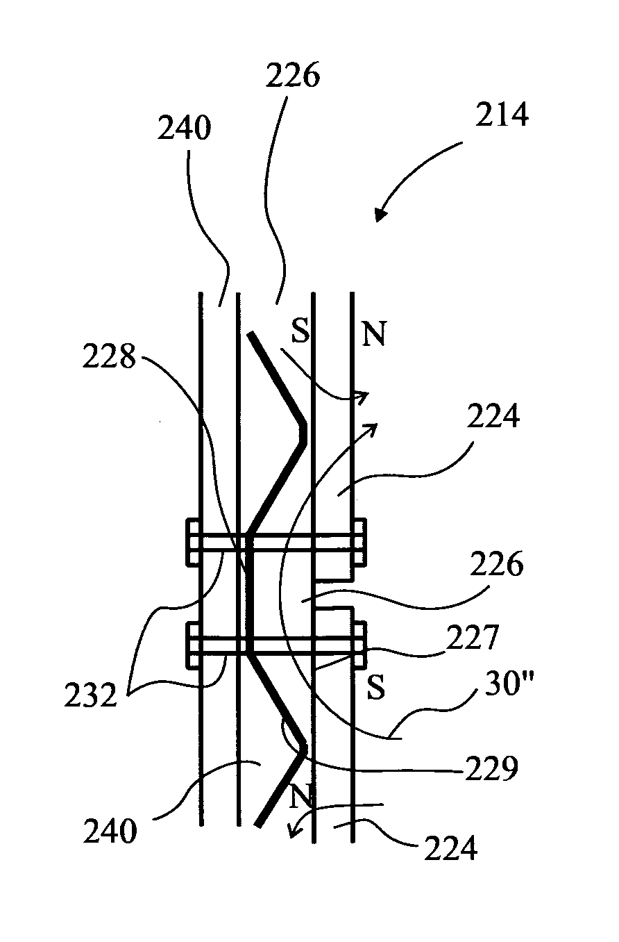
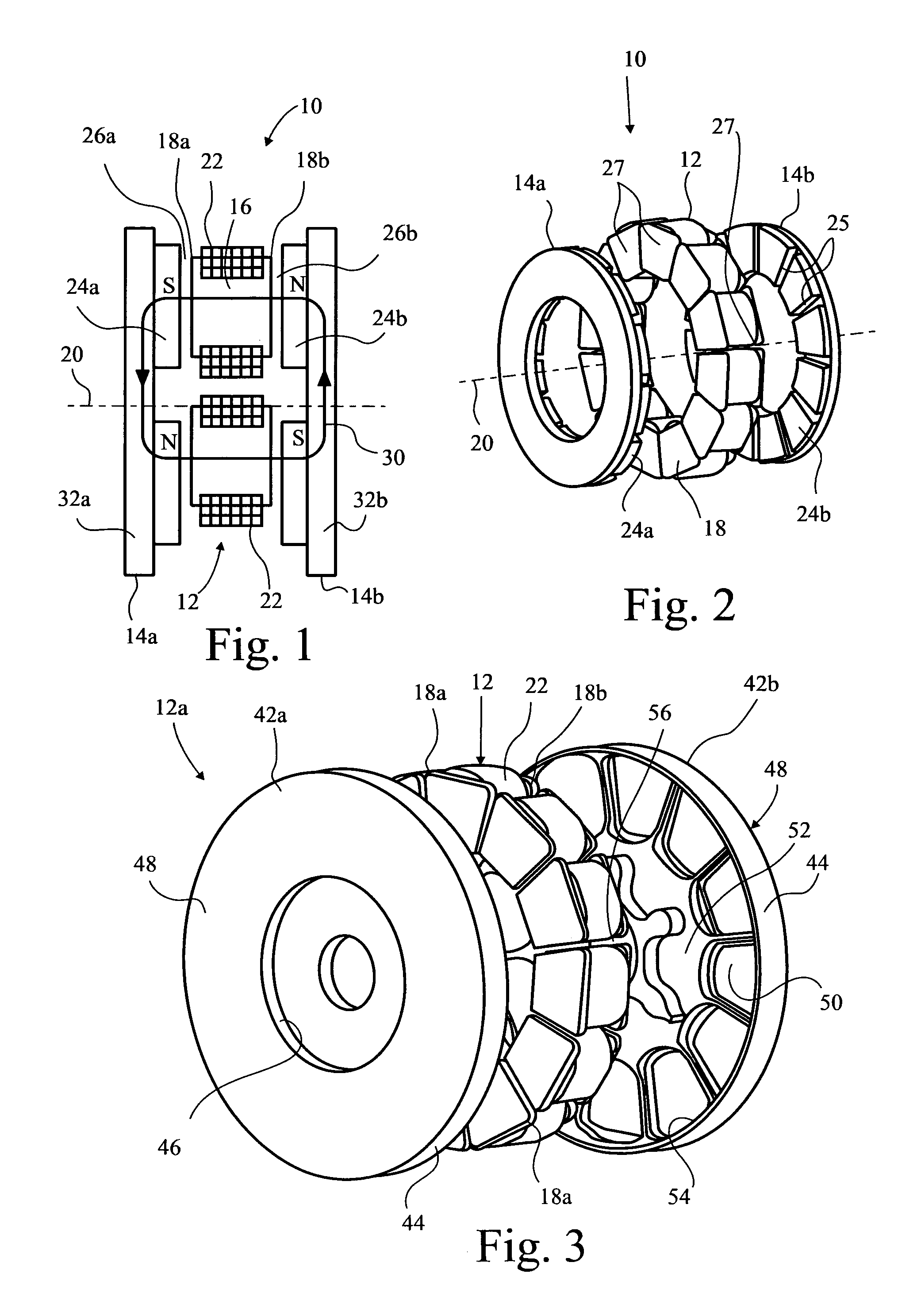
[0050]A yokeless and segmented armature machine 10 is illustrated schematically in FIG. 1. The machine 10 comprises a stator 12 and two rotors 14a, b. The stator 12 is a collection of separate stator bars 16 spaced circumferentially about a rotation axis 20 of the rotors 14a, b. Each bar 16 has its own axis 16a which is disposed parallel to the rotation axis 20. However, that is not absolutely essential. In an axial flux machine, the axis 16a is indeed parallel the rotation axis 20. However, it can be disposed at any angle thereto, even radially with respect to the rotation axis 20. The following discussion is in respect of an axial flux machine, but this should not be understood to be limiting in any sense and, where the context permits, the invention equally applies to other inclinations of the stator bars 16.

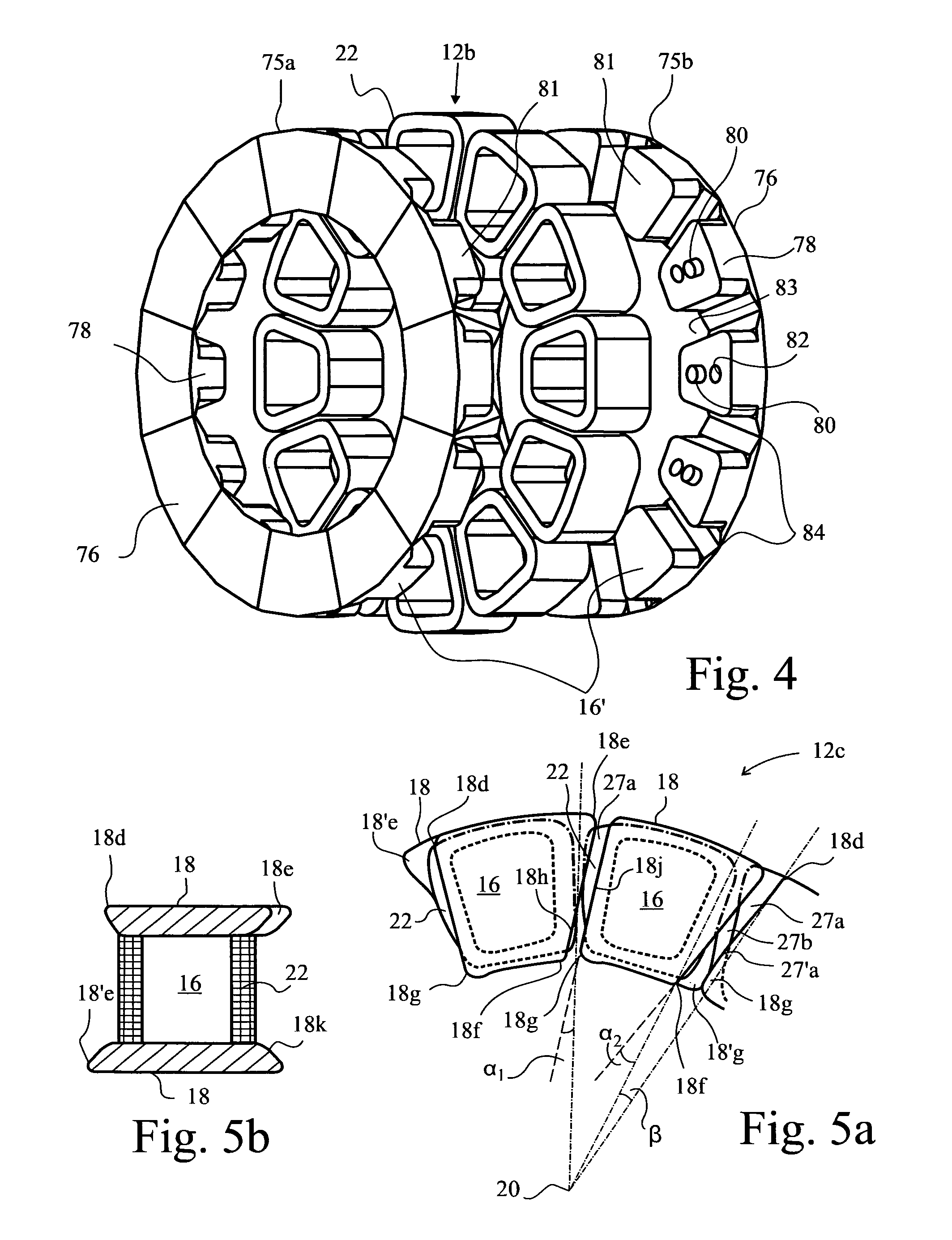
[0051]Each end of each stator bar is provided with a shoe 18a, b which serves a physical purpose of confining a coil stack 22, which stack 22 is preferably of square section ...


PUM


Abstract

An electric machine (10; 100) comprises a rotor (14) having permanent magnets (24) and a stator (12) having coils (22) wound on stator bars (16) for interaction with the magnets across an air gap (26a, b) defined between them. The rotor has two stages (14a, b) arranged one at either end of the bars. The bars have a shoe (18a, 8) at each end of each bar that links magnetic flux through the bars with said magnets on each stage. Adjacent shoes facing the same stage of the rotor have a high-reluctance shoe gap (27) between them; adjacent magnets on each stage of the rotor have a high-reluctance magnet gap (25) between them; and the shoe and magnet gaps (25, 27) are angled with respect to each other such that they engage progressively as the rotor rotates. Alternatively, the shoes facing each stage are in a ring of connected shoes such that the magnets experience a continuous reluctance that is at least 90% constant as a function of rotor position. The bars (16) and shoes (18) are formed separately from one another and at least a part of each is formed by moulding soft-iron particles so that the particles have a short dimension that is arranged transverse a reluctance-plane. The bars and shoes are assembled so that the reluctance-plane of the bar is parallel a longitudinal axis (16a) of the bar and said reluctance-plane of the shoe is transverse said longitudinal axis.

Description

CROSS REFERENCE TO RELATED APPLICATIONS[0001]This application is a 35 USC 371 national phase of International Application No. PCT / GB2010 / 050237 filed Feb. 12, 2010, which claims priority to U.K. Patent Application No. 0902390.4 filed Feb. 13, 2009, the contents of all of which are hereby incorporated herein by reference in their entirety.[0002]This invention relates to a permanent magnet electric machine comprising a stator and a rotor journalled for rotation in the stator. The stator is provided with coils wound on and the rotor is provided with permanent magnets to cooperate with the coils across an air gap between the rotor and stator. The machine may be either a motor or a generator and is in many embodiments an axial flux machine. In particular it relates to a yokeless and segmented armature machine, hereinafter termed a “Y machine”.BACKGROUND[0003]Woolmer and McCulloch [1] describe the topology of a Y machine, discussing its advantages of reduced iron in the stator enabling an...

Claims


Application Information

Patent Timeline
Patent Type & Authority Patents(United States)
IPC IPC(8): H02K29/03H02K21/12H02K21/24
CPCH02K21/24H02K29/03H02K2201/06H02K1/182H02K1/02H02K1/08H02K1/14H02K1/20H02K1/2793H02K5/1677H02K7/088H02K9/197H02K16/02
Inventor WOOLMER, TIM
Owner YASA LIMITED
Why Eureka
Try Eureka