Universal laparoscopic suturing device

a suturing device and universal technology, applied in the field of surgical instruments, can solve the problems of limiting the speed of surgery, preventing surgeons from performing more advanced surgical procedures in a minimally-invasive manner, and challenging laparoscopic suturing, so as to improve maneuverability, efficiency and functionality, and reduce the cost of operations

Inactive Publication Date: 2015-07-07
UNIV OF SOUTH FLORIDA
View PDF29 Cites 6 Cited by
  • Summary
  • Abstract
  • Description
  • Claims
  • Application Information

AI Technical Summary

Benefits of technology

[0010]The novel laparoscopic suture assist device opens widely to suture large areas of tissue. It includes a preformed needle that drives any generic suture through the tissue. The device also enables suture to be placed as a single stitch, or as a running stitch. This increases flexibility for the surgeon and decreases operative expense. The device can be used to suture multiple times throughout the surgical procedure. The device also has a unique design that allows it to open wider than the diameter of the shaft of the instrument, to maximize the area of laparoscopic suturing available to the surgeon.
[0019]Still another object is to provide more options to laparoscopic surgeons and to reduce the expense of operations by providing instruments with improved maneuverability, efficiency and functionality.

Problems solved by technology

Laparoscopic suturing is a challenging skill to master for surgeons performing laparoscopic surgery.
It is often the rate-limiting step that prevents surgeons from performing more advanced surgical procedures in a minimally-invasive manner.
Laparoscopic suturing is challenging for several reasons.
Second, grasping the small needle and placing the needle through tissue without wristed motion is very challenging since surgeons operate using elongated rigid shafts.
Moreover, tying an appropriate knot after the suture is placed, and getting the knot secured to the appropriate tissue from a distance through small laparoscopic ports, is technically challenging.
Each of the known devices has various advantages and disadvantages, and most of these devices require the use of specific suture exclusively designed for the device.
Since the suture for each of these devices is limited, the surgeon's choice of suture material is also limited.
These specific sutures are also very expensive and reduce flexibility of suture available to the surgeon.
The small needle can break during laparoscopic suturing and the small needle also limits the size of tissue that can be sutured.

Method used


Image

  • Universal laparoscopic suturing device
  • Universal laparoscopic suturing device
  • Universal laparoscopic suturing device

Examples


Embodiment Construction

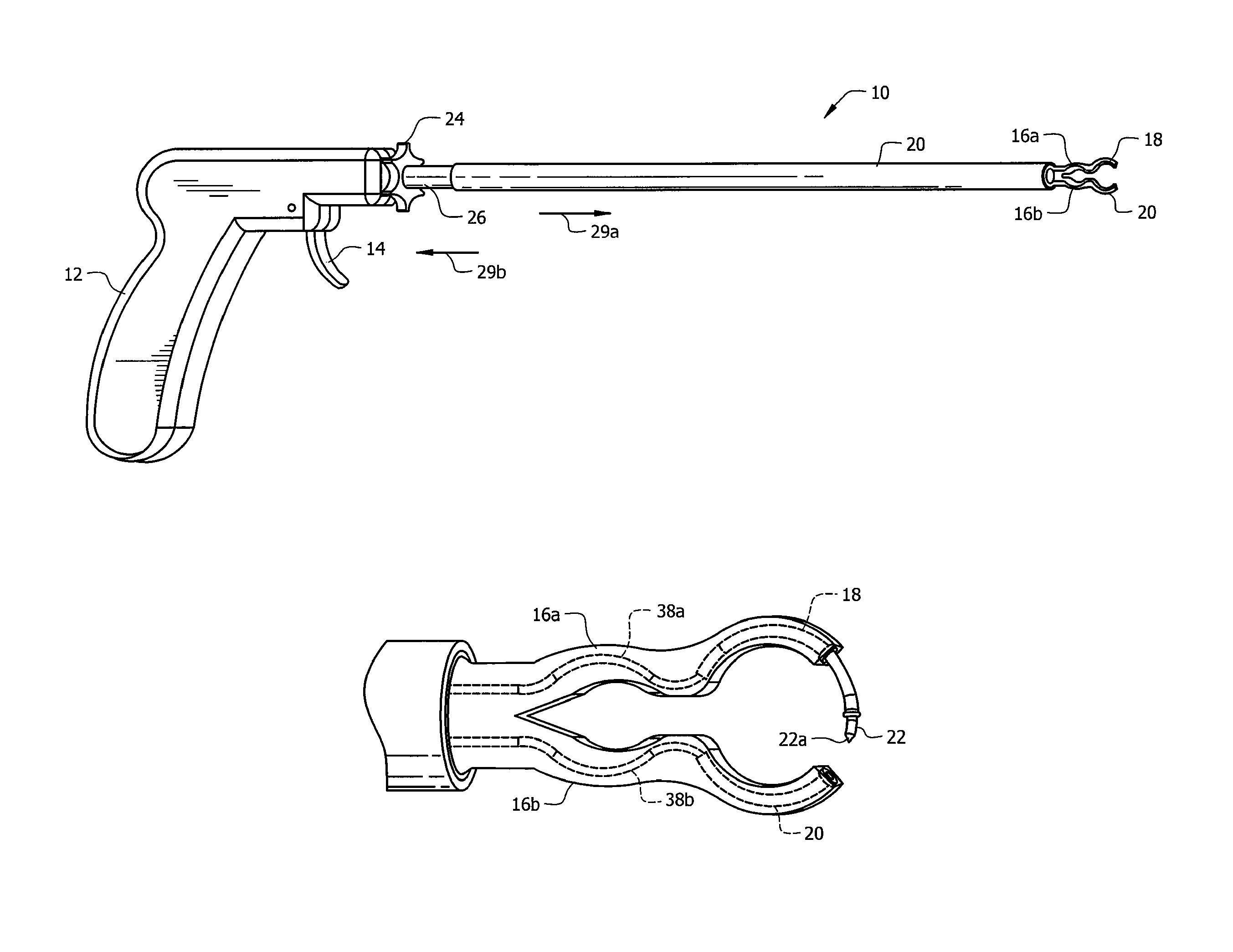
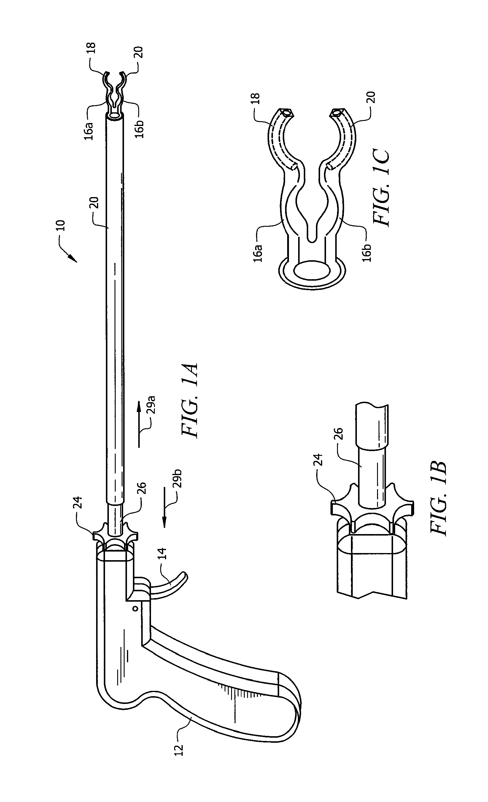
[0045]FIG. 1A depicts an illustrative embodiment of the novel laparoscopic suture assist device which is denoted as a whole by the reference numeral 10.

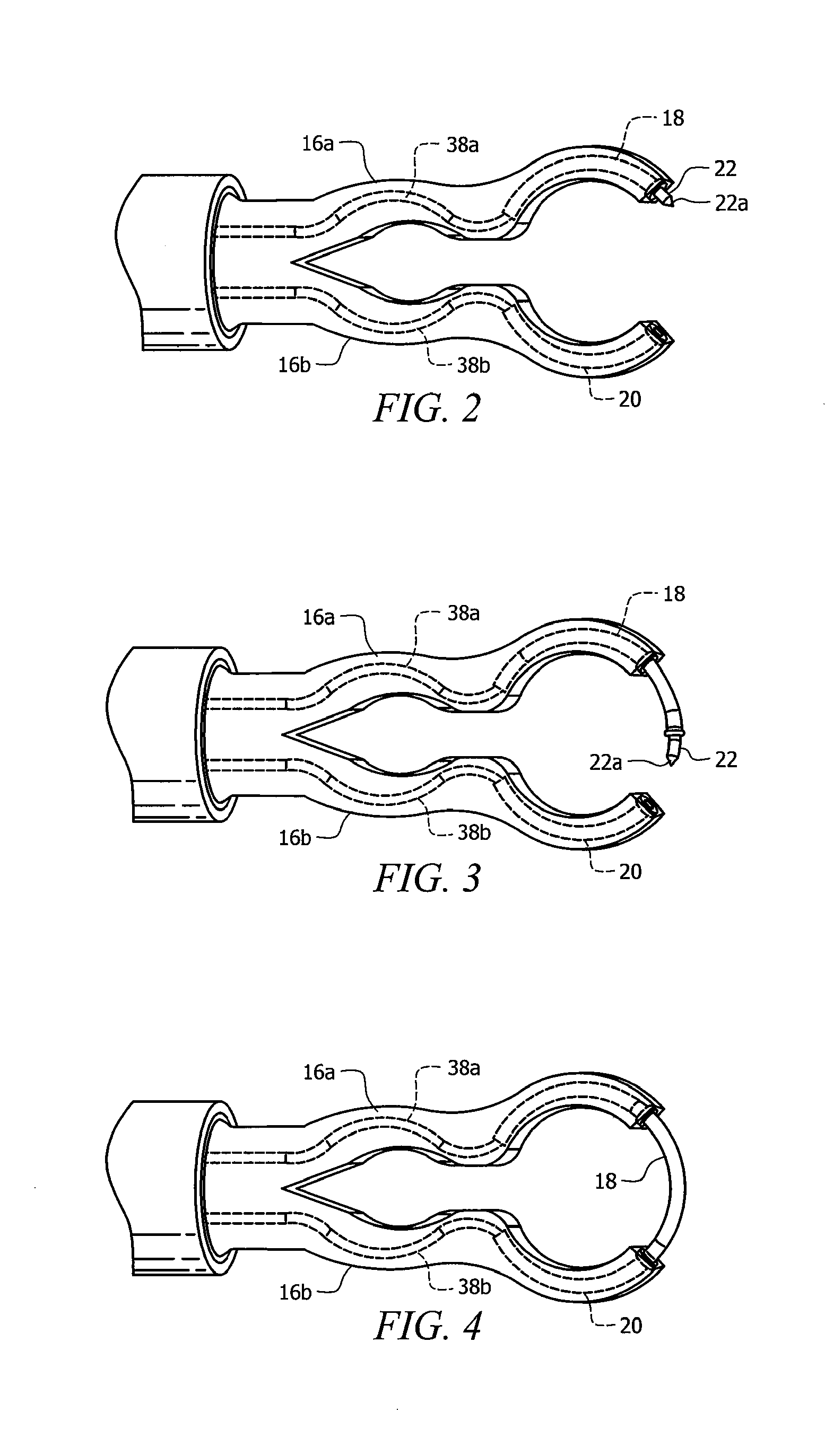
[0046]Device 10 is an eleven and a half millimeter (11.5 mm) instrument that includes nine main parts. As depicted in FIGS. 1A, 1B, 1C, 2, and 3 those parts are handle 12, pusher 14, arms 16a, 16b, needle carrier 18, needle holder 20, needle 22, toggle knob 24, shaft 26 and sheath 28.

[0047]As will become clear as this disclosure continues, needle carrier 18 and needle holder 20 reverse roles as device 10 is used, i.e., needle 22 is carried by needle carrier 18, inserted into needle holder 20, and needle carrier is then withdrawn, leaving the needle in needle holder 20. Needle holder 20 then becomes the carrier as the needle is carried to needle carrier 18 and inserted thereinto with needle holder 20 then being withdrawn. This role reversal is repeated as needed throughout a suturing procedure.

[0048]Needle 22 is truncate in extent and...


PUM


Abstract

A laparoscopic suturing device includes a handle and a shaft mounted to the handle. A toggle knob is adapted to rotate the shaft about its longitudinal axis. A pair of opposed jaws, each having a hollow structure, open and close relative to one another. A needle carrier and a needle holder are respectively slideably disposed in a lumen of a first and a second jaw. A needle has first and second pointed ends and is adapted to be press fit into the lumen of the first jaw with the first pointed end exposed and alternatively into the lumen of the second jaw with the second pointed end exposed. A spring-loaded pusher advances and retracts the needle carrier when the toggle knob is in a first position and advances and retracts the needle holder when in a second position. The tool assists a surgeon in suturing tissue captured between the jaws.

Description

BACKGROUND OF THE INVENTION[0001]1. Field of the Invention[0002]This invention relates, generally, to surgical instruments. More particularly, it relates to suturing and knot tying instruments for use during minimally invasive surgery.[0003]2. Description of the Prior Art[0004]Laparoscopic suturing is a challenging skill to master for surgeons performing laparoscopic surgery. It is often the rate-limiting step that prevents surgeons from performing more advanced surgical procedures in a minimally-invasive manner. Laparoscopic suturing is challenging for several reasons. First, the surgeon is operating in three dimensional space while viewing the procedure on a two dimensional screen. Second, grasping the small needle and placing the needle through tissue without wristed motion is very challenging since surgeons operate using elongated rigid shafts. Moreover, tying an appropriate knot after the suture is placed, and getting the knot secured to the appropriate tissue from a distance t...

Claims


Application Information

Patent Timeline
Patent Type & Authority Patents(United States)
IPC IPC(8): A61B17/04A61B17/062A61B1/00A61B17/12A61B1/313A61B17/06A61B17/00
CPCA61B17/0469A61B1/00066A61B1/3132A61B17/0625A61B2017/00367A61B2017/0609
Inventor HART, STUARTONAL, SINANLAI-YUEN, SUSANA K.
Owner UNIV OF SOUTH FLORIDA
Why Eureka
Try Eureka